Carrier envelope phase stabilization of an optical amplifier

Active Publication Date: 2011-01-27
COHERENT INC
View PDF8 Cites 30 Cited by
  • Summary
  • Abstract
  • Description
  • Claims
  • Application Information

AI Technical Summary

Problems solved by technology

It has been found, however, that if a pulse from a CEP-stabilized oscillator is amplified in a chirped pulse amplification arrangement, wherein the input pulses from the oscillator are tempo

Method used


Image

  • Carrier envelope phase stabilization of an optical amplifier
  • Carrier envelope phase stabilization of an optical amplifier
  • Carrier envelope phase stabilization of an optical amplifier

Examples


Embodiment Construction

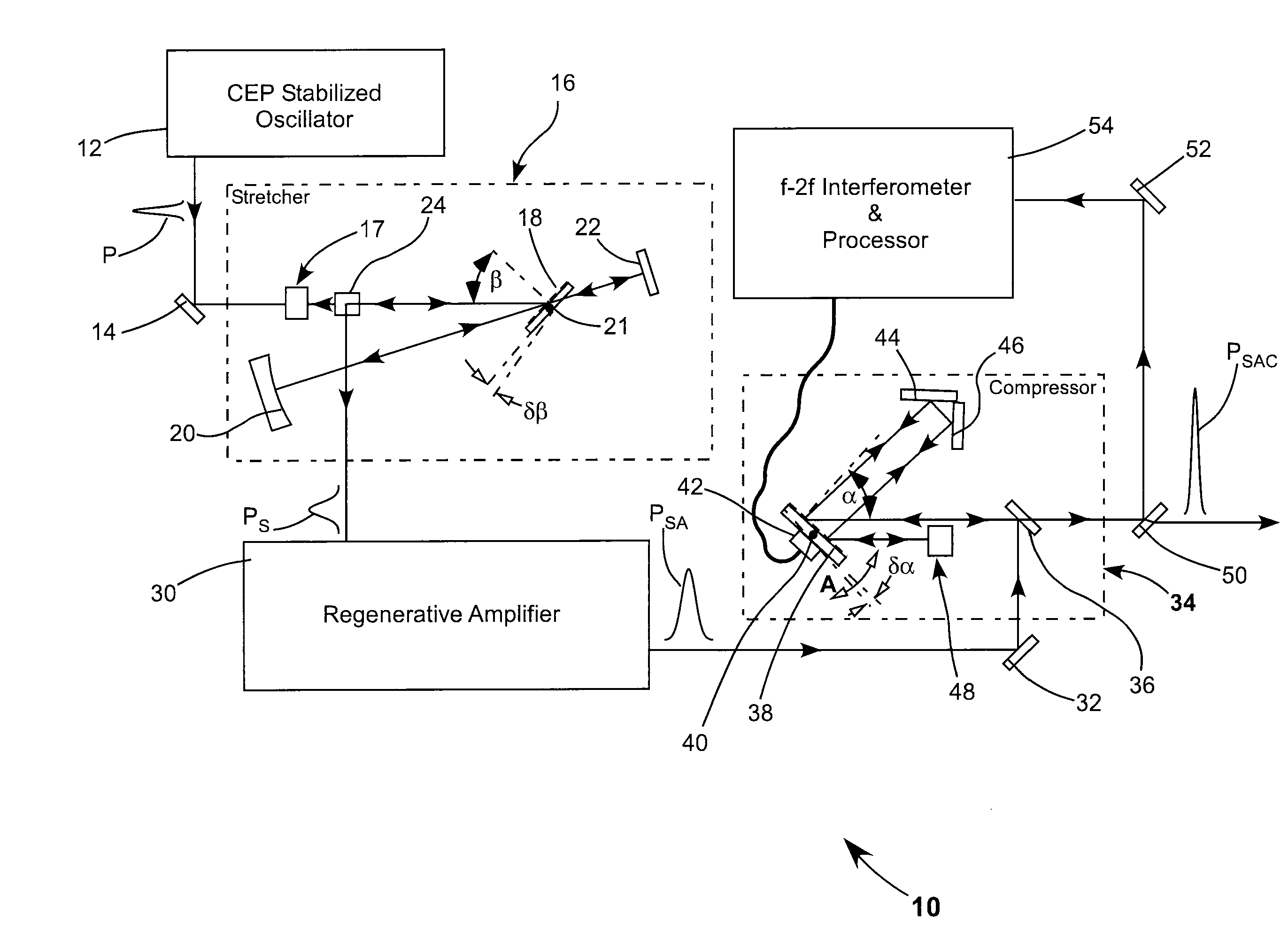
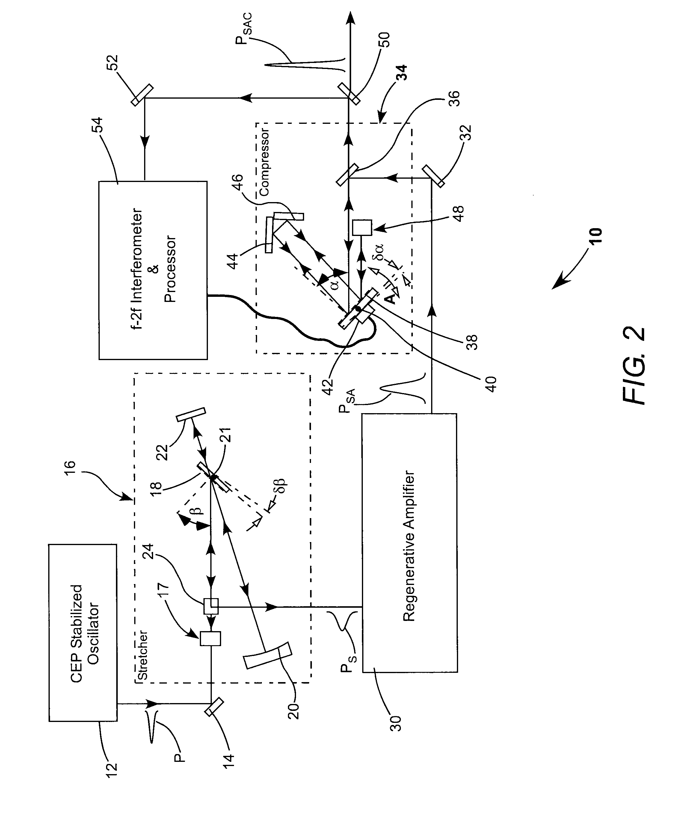
[0010]FIG. 2 schematically illustrates a preferred embodiment 10 of laser apparatus in accordance with the present invention. Apparatus 10 includes a CEP stabilized master oscillator (laser) 12 for providing seed-pulses for further amplification. One laser suitable for laser 12 is a model Micra-CEPS™ available from Coherent, Inc., of Santa Clara, Calif.

[0011]Laser 12 delivers a seed pulse P to be amplified via a turning mirror 14 into a pulse stretcher 16 for temporal pulse stretching. Stretcher 16 includes a retro-reflecting mirror pair 17 (only one mirror of the pair is visible in FIG. 2). Pulse stretcher 16 also includes a diffraction grating 18, a concave mirror 20, and plane mirrors 22 and 24.

[0012]Seed pulse P enters the stretcher through a space between the mirrors of the retro-reflecting mirror-pair 17 and is diffracted by grating 18. The pulse then follows a path from grating 18 to mirror 20; from mirror 20 to mirror 22; from mirror 22 back to mirror 20; from mirror 20 to g...


PUM


Abstract

A laser and amplifier combination delivers a sequence of optical pulses. Pulses from the laser are temporally stretched by a pulse stretcher before amplification and temporally compressed by a pulse compressed after amplification. The pulse stretcher includes a diffraction grating on which pulses being compressed are incident. An arrangement is provided for measuring the carrier-envelope phase of the pulses and adjusting the incidence angle of pulses on the grating cooperative with the measurement such that the carrier envelope phase of the pulses in the sequence is about constant.

Description

PRIORITY CLAIM[0001]This application claims priority of U.S. Provisional Application No. 61 / 228,461, filed Jul. 24, 2009, assigned to the assignee of the present invention and the complete disclosure of which is hereby incorporated by reference.TECHNICAL FIELD OF THE INVENTION[0002]The present invention relates in general to laser oscillator amplifier arrangements for delivering femtosecond pulses. The invention relates in general to such arrangements wherein a laser pulse is temporally stretched prior to amplification and the amplified pulse is temporally compressed before delivery.DISCUSSION OF BACKGROUND ART[0003]Optical pulses having a duration of a few femtoseconds or less may include only a few optical cycles at a fundamental carrier frequency of the pulse within an envelope of the pulse. A pulse-envelope typically has a Gaussian or Sech-squared form. The peak power within the envelope will depend on the phase of the carrier cycles relative to the envelope. This is referred to...

Claims


Application Information

Patent Timeline
IPC IPC(8): H01S3/00
CPCH01S3/0014H01S3/0057H01S2301/08H01S3/235H01S3/1307
Inventor LI, CHENGQUAN
Owner COHERENT INC
Why Eureka
Try Eureka