
Data communications

Active Publication Date: 2011-01-27
BT NEWGATE
View PDF10 Cites 9 Cited by
  • Summary
  • Abstract
  • Description
  • Claims
  • Application Information

AI Technical Summary

Benefits of technology

[0014]Preferably the predetermined period of time is at least greater than one hour and most preferably it is of the order of a day or a week. Preferably the predetermined amount of variation which, if exceeded, causes a rate capped profile to be applied to a connection is at least 3 dB. By fully rate adaptive profile, it is meant a profile for which the maximum rate specified is the maximum rate which the aggregation transceiver device (or the combination of the aggregation transceiver device and the end user device—such as a DSL modem) can support. This is often based on the nature of the protocol being employed for the connection—e.g. many DSLAM's operating using ADSL 1 have a maximum rate which they can support even in ideal noise conditions of 8128 Kbits because of the type of framing which they employ, whilst DSLAM's operating in ADSL 2+ mode have a maximum rate of 24 Mbit / s, etc. By rate capped profile, it is meant a profile which sets an upper limit connection rate which is significantly less than the maximum rate supported by the equipment under ideal circumstances. By specifying an upper limit rate which is less than the maximum rate theoretically supportable by the equipment, it ensures that even if a very low level of noise (i.e. a very high level of SNR) is measured by the equipment at the time of synchronising the connection, it will still not connect as at high a rate as it would if it were running under a fully rate adaptive profile for a given target SNR margin. This protects against lines which, even if they were on a profile with a very high SNR margin target might still connect up at too high a speed if they happened to synchronise at a time when the line was experiencing very low levels of noise, from connecting up at too high a rate and then later experiencing much higher levels of noise resulting a loss of connection. Additionally it would benefit such lines by enabling them to use a lower SNR margin target than would otherwise be possible, which would enable the lines to connect at a higher rate than they otherwise would (if they had a higher SNR margin target) if they happened to synchronise at a time when they were experiencing very high levels of noise (i.e. at the peak of the medium term variation in noise experienced by the line—where medium term indicates a period of a day or a week or so).
[0019]The upper rate may be selected in accordance with a threshold rate comprising the highest data rate at which the connection was operated in step (a) during a trial period with a connection performance (i.e. a stability of the connection in terms of number of errors, re-synchronisations, etc.) determined to be within acceptable limits for a predetermined period, preferably over the entire trial period. Since an algorithm according to an embodiment of the present invention in some circumstances operates to maximise the data rate by reducing the rate during the trial period until the line is stable, the threshold rate is sometimes referred to as the minimum line rate since this is, in practice, the lowest rate that the line operates at over the predetermined trial period; the line rate will not drop any further once stability is achieved. The predetermined trial period may be a medium term period not less than twelve hours. In the embodiment described herein, the connection performance is assessed daily on the basis of the previous twenty four hours. The upper rate is preferably selected to be below said minimum line rate, i.e. the highest rate at which the connection was operated in step (a) with stability over the predetermined period.

Problems solved by technology

It is particularly useful when operating DSL connections at close to their maximum speed as occurs in rate adaptive connections because, under these conditions, external noise affecting the transmitted signal can cause the transceivers to be unable to successfully recover the signal to be transmitted with sufficient reliability to enable the connection to be maintained.
However, since the noise may comprise components of crosstalk, impulse noise and Repetitive Electrical Impulse Noise (REIN), all of which can vary with time the SNR measured at synchronisation may well not accurately reflect the SNR going forward in time.
An incorrect noise estimation may result, in one direction (i.e. if the overall level of noise over all channels increases from the time that the synchronisation was performed by more than the amount catered for by the SNR target margin), in the DSLAM employing a rate which still results in instability or, in the other direction (i.e. if the overall noise reduces or does not ever increase as much as the SNR target margin catered for), one which is too conservative and so results in a poor data rate.
If the noise varies over relatively short periods, it is particularly difficult to estimate the noise and so SNR.
Although the DSLAM may estimate the noise over a period which is adequate to observe such short term variation, the statistics of the noise in terms of peak to mean ratio and other measures can make it difficult to correctly compute the maximum available data rate that can be achieved.
If the noise varies over longer time scales, it may be that the estimate used when the DSLAM established a connection, although correct at the time, is incorrect a short time later causing the connection to fail and require re-synchronisation.
It may even be that the DSLAM transceiver is itself poorly implemented and so incorrectly estimates the noise.

Method used


Image

  • Data communications
  • Data communications
  • Data communications

Examples


Embodiment Construction

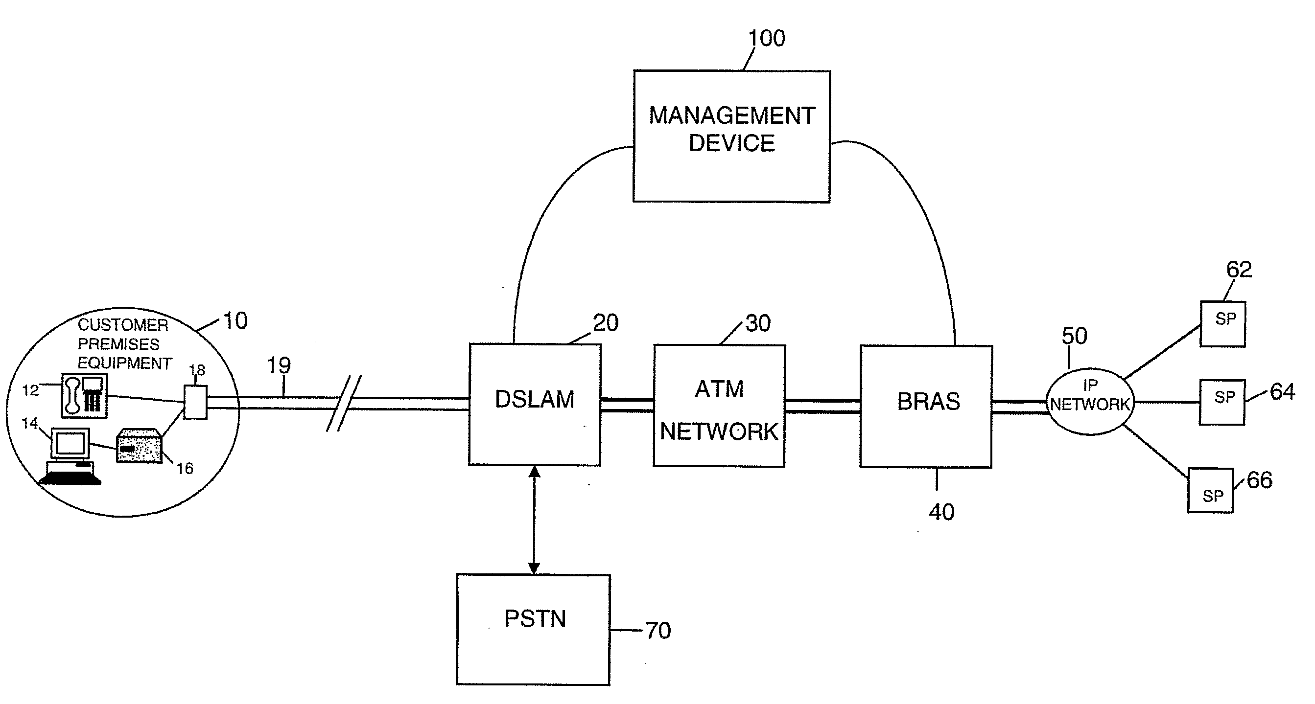
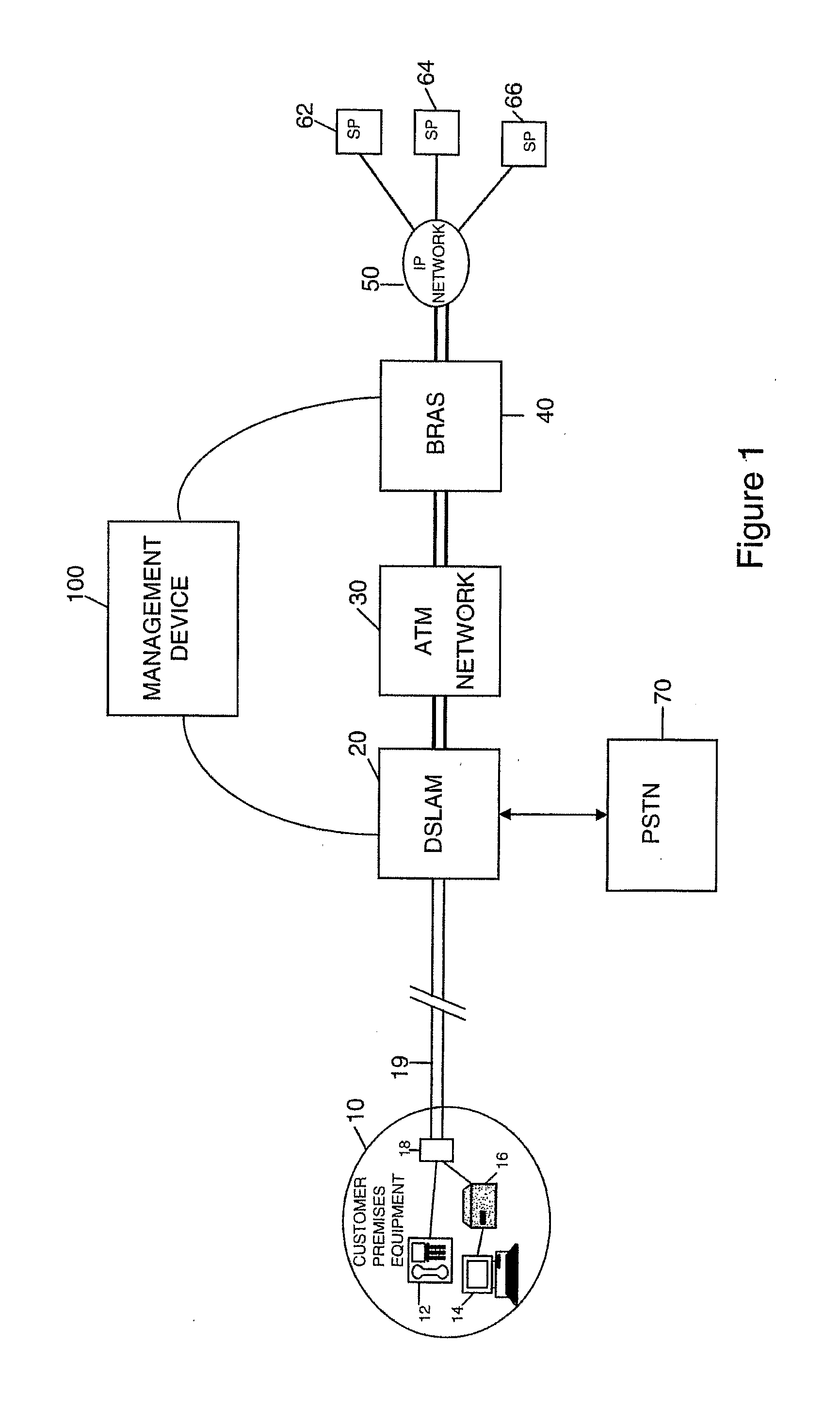
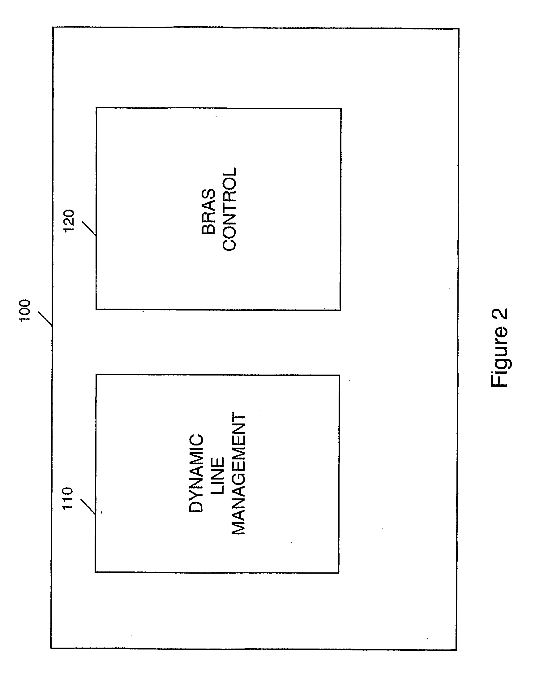
[0029]Referring to FIG. 1, the embodiment described below uses a management device 100 to perform two principal functions, namely Broadband Access Remote Server (BRAS) provisioning and Dynamic Line Management (DLM). BRAS provisioning is described very briefly in this application, for the sake of completeness, but is described in greater detail in co-pending International patent applications GB2006 / 002826 and GB2006 / 002818. Regarding the DLM function 110, this is used in the embodiment to control the downstream speed, i.e. data rate, of the ADSL connections controlled by the management device 100 to achieve stability and so minimise the need for re-synchronisations caused by noise on the connection.

[0030]In overview, the role of the DLM function 110 of the management device 100 is to ensure that the ADSL connections are as stable as possible, i.e. with as few errors and, in particular, as few re-synchronisations as possible whilst still providing a good connection for the end user in...


PUM


Abstract

In a method and system for operating an ADSL access network which has a plurality of data connections (19) between the access network and end user devices (10), and in which the access network controls the rate at which data is transferred between the user devices and an onward connection (50), the access network stores a plurality of capped profiles each of which specifies a respective upper data rate to which the connection is limited and which is below the maximum achievable rate for the connection. The access network operates using a Dynamic Line Management (DLM) algorithm which, for a given data connection, operates to enable data transfer at a variable data rate up to the maximum rate, monitors the error performance and signal to noise margin variation for different data rates and, in the event that one or both are outside respective limits for a predetermined period, selects and applies one of the capped profiles to limit the upper data rate, selection being determined by the highest data rate achieved for which the error performance was within acceptable limits.

Description

FIELD OF THE INVENTION[0001]The present invention relates to data communications, and particularly, though not exclusively, to the management of an access network including Digital Subscriber Line (DSL) connections.BACKGROUND TO THE INVENTION[0002]A relatively recent development in the operation of access networks employing DSL connections is to move from fixed rate connections (where a user contractually agrees with the network operator / service provider a fixed rate (e.g. 2 Mbit / s) at which the DSL connection will operate and the network always attempts to set up a connection at exactly this speed) to rate adaptive connections where the DSL connection attempts to connect up at the fastest achievable (but reasonably stable) speed of connection (e.g. up to 8 Mbit / s).[0003]Dynamic Line Management (DLM) is a technique for improving the stability of DSL connections. It is particularly useful when operating DSL connections at close to their maximum speed as occurs in rate adaptive connec...

Claims


Application Information

Patent Timeline
IPC IPC(8): H04L12/26
CPCH04L1/0002H04L5/14Y02B60/31H04L47/10H04L47/263H04L27/2601Y02D30/50
Inventor CROOT, CHRISTOPHER M.LINNEY, TREVOR P.EVERETT, PHILIP A.COOK, JOHN W.PICKERING, ASHLEY
Owner BT NEWGATE
Learn More