Catheter-based off-axis optical coherence tomography imaging system

Active Publication Date: 2011-01-27
AVINGER
View PDF105 Cites 156 Cited by
  • Summary
  • Abstract
  • Description
  • Claims
  • Application Information

AI Technical Summary

Benefits of technology

[0028]Also described herein are Optical Coherence Tomography (OCT) catheter devices for visualizing a body lumen by rotation of the catheter and an off-axis optical fiber within the catheter that include: a catheter body having an elongate proximal to distal length; an optical fiber fixed to a distal end region of the catheter body and extending the length of the catheter body along a path that is off-axis of the elongate length of the catheter body;

Problems solved by technology

However, successful visualization, particularly visualization into a tissue volume, has proven elusive.
Currently available systems are poorly adapted for real-time imaging, particularly for use in catheters including atherectomy catheters.
However, such embodiments take up a lot of space, so much so that they may not be practical for use in conjunction with a therapeutic embodiment such as an atherectomy device.
Two problems immediately ensue from this arrangement.
First, the break in the fiber and the re-imaging optics create several surfaces with potentially very large return losses (back-reflections) compared to the usual OCT reference reflection.
This makes the device difficult to use with common-path interferometry, as the interferometer will index off the first substantial reflection.
One cannot simply make the reference reflection brighter than these surfaces, as (a) this would then create a reference reflection that could saturate the detector if it needed to be greater than, for example, 20 microWatts, and (b) the strong reflections present in the proximal optical path could still lead to artifacts in the OCT image, as these reflective surfaces would still be orders of magnitude brighter than the signal from the tissue.
Such a high level of accuracy drives up the cost of the device significantly, which is something of particular concern in a single-use disposable device.
This solut

Method used


Image

  • Catheter-based off-axis optical coherence tomography imaging system
  • Catheter-based off-axis optical coherence tomography imaging system
  • Catheter-based off-axis optical coherence tomography imaging system

Examples


Embodiment Construction

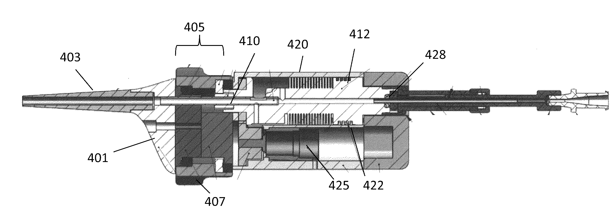
[0073]Described herein are OCT catheters and imaging systems using them, including methods for using them to image. In general, an OCT catheter as described herein is a flexible elongate catheter that includes an optical fiber for OCT imaging that extends the length of the catheter. The pathway taken by the optical fiber is displaced from the central longitudinal (proximal-distal) axis of the catheter, and thus may be referred to as off-axis. The catheter body is typically rotationally coupled to a handle portion so that the catheter body and the optical fiber rotate together relative to the handle.

OCT Catheters Having Off-Axis Optical Fibers

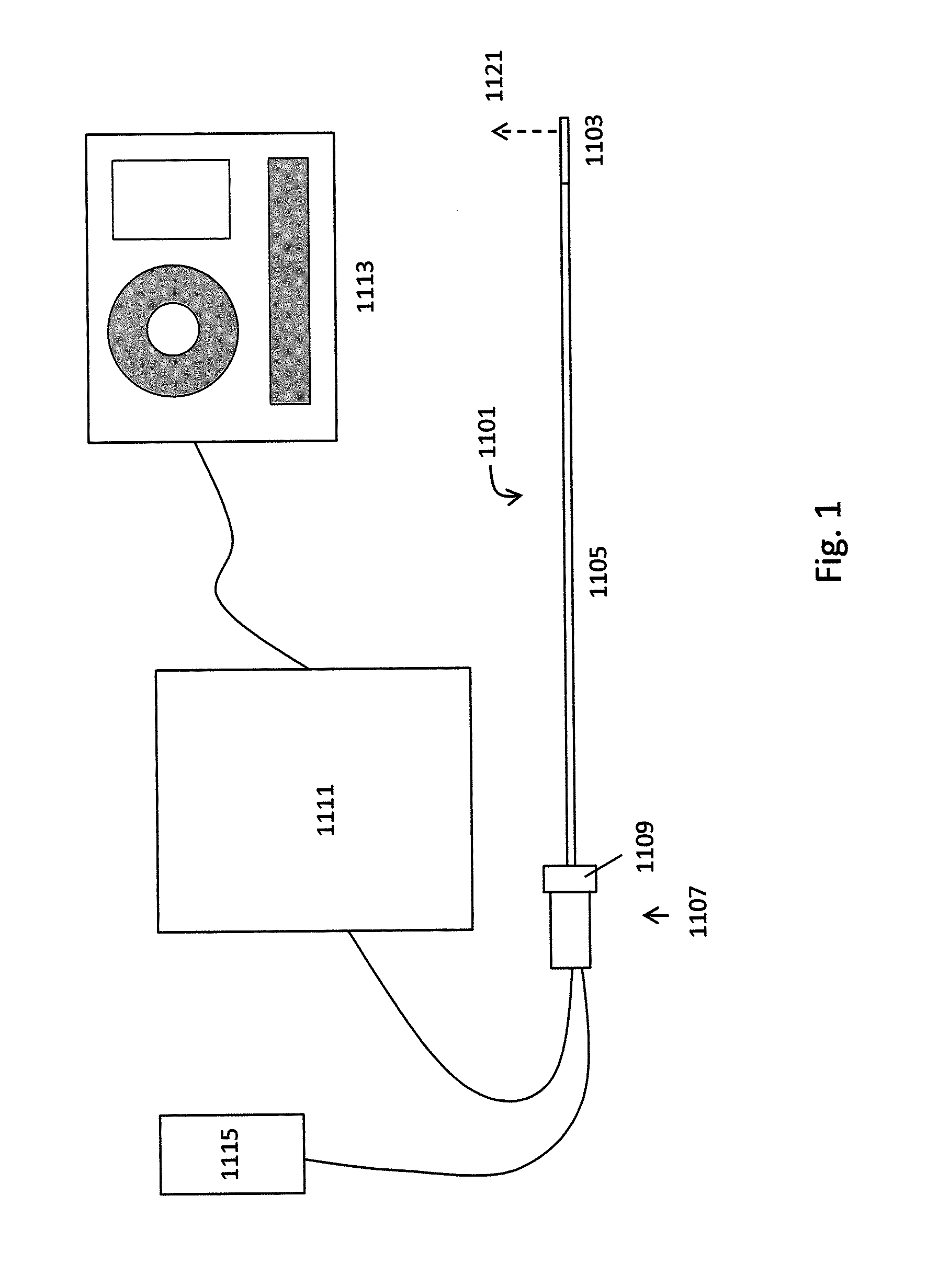
[0074]FIG. 1 illustrates one variation of an OCT catheter having an off-axis optical fiber that may form part of an OCT imaging system configured as described herein. In this example, the device includes a catheter 1101 having a distal end 1103 that includes a one-dimensional OCT sensor (typically configured as a common-path interferometry devic...


PUM


Abstract

Catheter-based Optical Coherence Tomography (OCT) systems utilizing an optical fiber that is positioned off-axis of the central longitudinal axis of the catheter have many advantage over catheter-based OCT systems, particularly those having centrally-positioned optical fibers or fibers that rotate independently of the elongate body of the catheter. An OCT system having an off-axis optical fiber for visualizing the inside of a body lumen may be rotated with the body of the elongate catheter, relative to a handle portion. The handle may include a fiber management pathway for the optical fiber that permits the off-axis optical fiber to rotate with the catheter body relative to the handle. The system may also include optical processing elements adapted to prepare and process the OCT image collected by the off-axis catheter systems described herein.

Description

CROSS REFERENCE TO RELATED APPLICATIONS[0001]This application claims priority to U.S. Provisional patent application Ser. No. 61 / 222,238, titled “CATHETER FOR INTRALUMINAL CIRCUMFERENTIAL IMAGING WITH ROTATION ANGLE AND LONGITUDINAL POSITION ENCODING,” filed on Jul. 1, 2009, and U.S. Provisional patent application Ser. No. 61 / 244,408, titled “CATHETER-BASED OPTICAL COHERENCE TOMOGRAPHY IMAGING SYSTEM” and filed on Sep. 21, 2009.[0002]This application may also be related to pending U.S. patent application Ser. No. 12 / 790,703, titled “OPTICAL COHERENCE TOMOGRAPHY FOR BIOLOGICAL IMAGING,” filed on May 28, 2010.INCORPORATION BY REFERENCE[0003]All publications and patent applications mentioned in this specification are herein incorporated by reference in their entirety to the same extent as if each individual publication or patent application was specifically and individually indicated to be incorporated by reference.FIELD OF THE INVENTION[0004]Described herein are imaging catheters. In ...

Claims


Application Information

Patent Timeline
IPC IPC(8): A61B6/00
CPCA61B5/0062A61B5/0066A61B5/0073A61B5/0084A61B5/6852A61B5/7257A61B5/02007
Inventor SPENCER, MAEGAN K.WHITE, CHRISTOPHER B.MCNALL, CHARLES W.JACKSON, DENNIS W.ZUNG, MICHAELSPINELLI, NICHOLAS J.NGO, BENJAMINLUMABAS, EVANGELINECHAN, KIN F.BLACK, JOHN F.ROSENTHAL, MICHAEL H.SIMPSON, JOHN B.
Owner AVINGER
Why Eureka
Try Eureka