

DC Power Converting Circuit and Method Thereof
- Summary
- Abstract
- Description
- Claims
- Application Information
AI Technical Summary
Benefits of technology
Problems solved by technology
Method used
Image

Examples
first embodiment
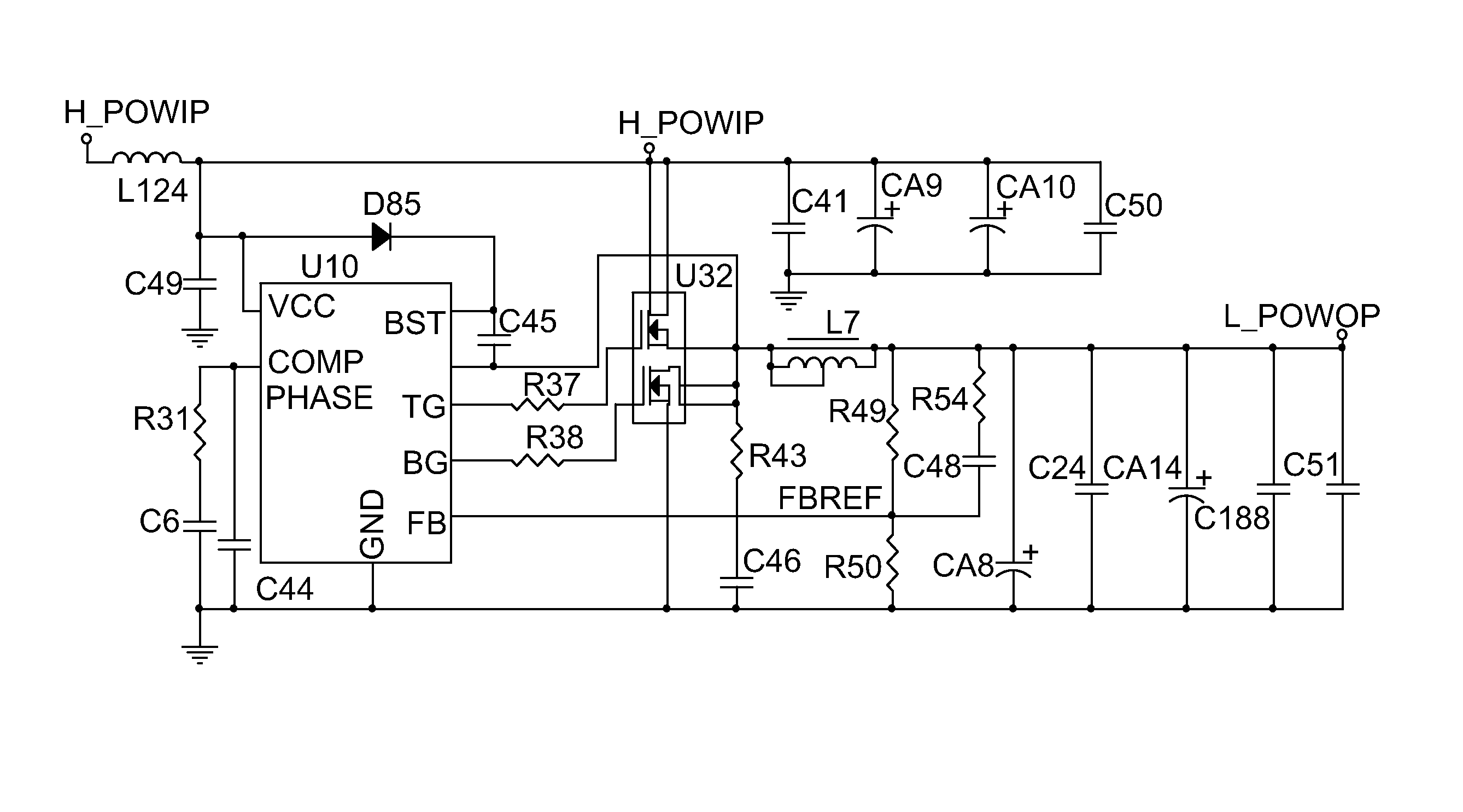
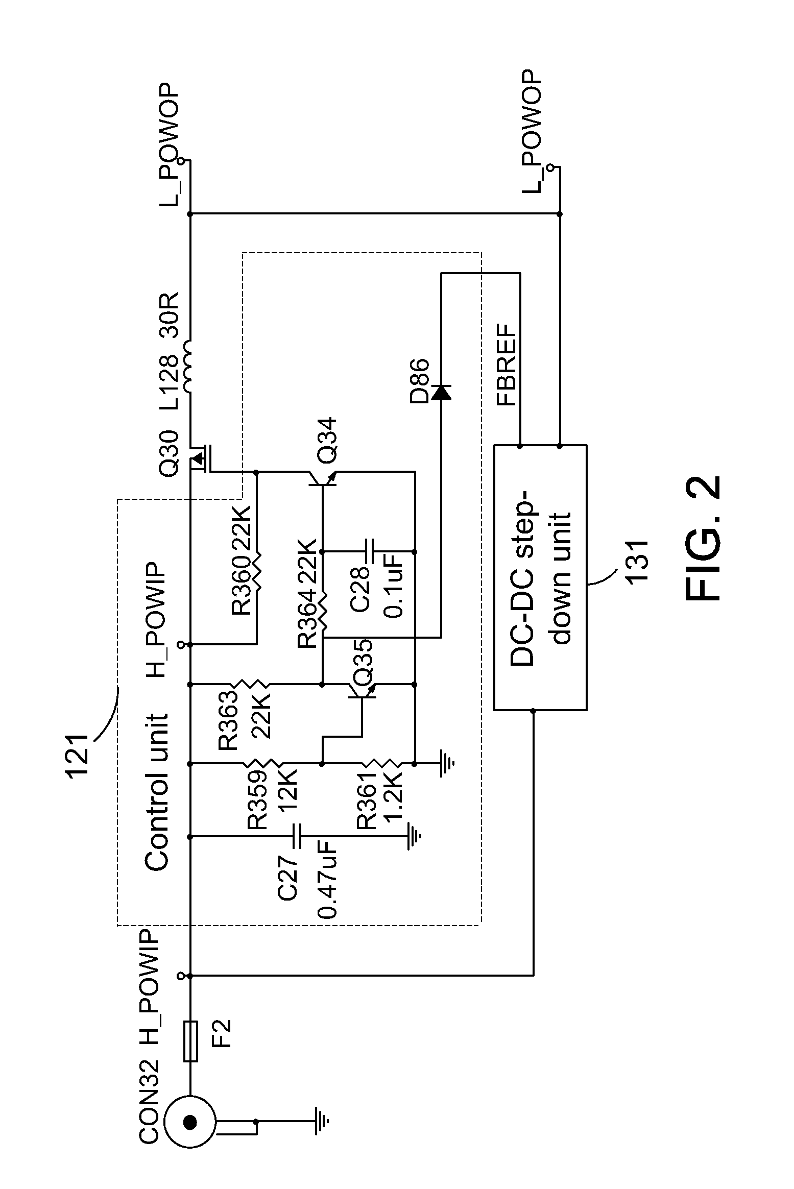
[0025]FIG. 2 is a schematic diagram of a DC power converting circuit in accordance with the present invention. A fuse F2 is coupled between a power input socket CON 32 and a DC input end H_POWIP. A direct path, comprising a transistor Q30 and an inductor L128, couples between the DC input end H_POWIP and a DC output end L_POWOP, and a step-down voltage path, comprising a DC-DC step-down unit 131 (enabled / disabled by logic level signals), is coupled between the DC input end H_POWIP and the DC output end L_POWOP as well. A dotted frame represents the control unit 121. A control signal FBREF controls operations of the DC-DC step-down unit 131, i.e., the control signal FBREF provides a logic level voltage to operate the DC-DC step-down unit 131.
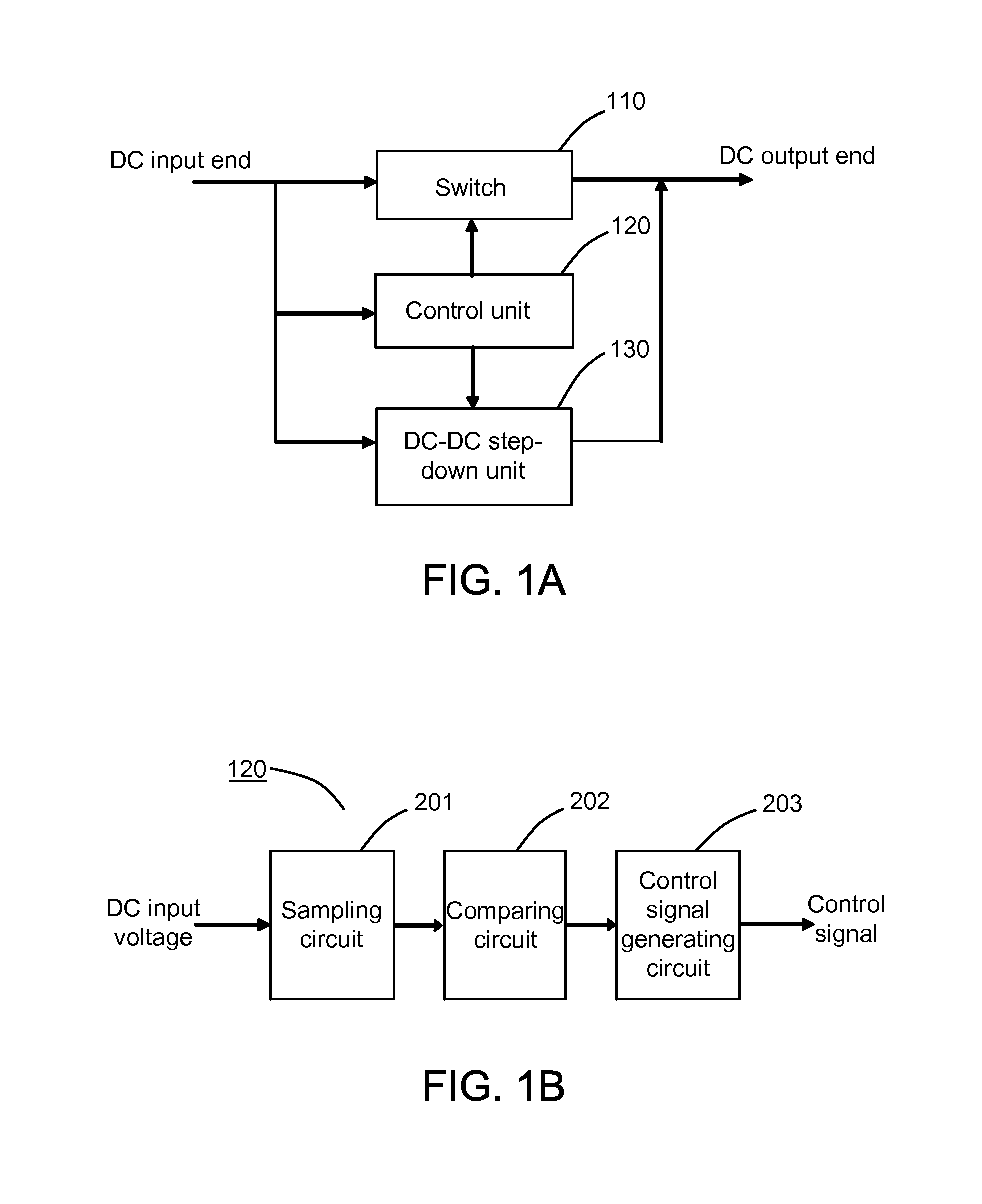
[0026]In this embodiment, the sampling circuit 201 comprises resistors R359 and R361; the comparing circuit 202 comprises a resistor R363 and an negative-positive-negative (NPN) transistor Q35; the control signal generating circuit 203 comprises ...
second embodiment
[0034]FIG. 3 is a schematic diagram of a DC power converting circuit in accordance with the present invention. A fuse F1 is coupled between a power input socket CON 31 and a DC input end H_POWIP. A direct path, comprising a transistor Q29 and an inductor L126, couples between the DC input end H_POWIP and a DC output end L_POWOP, and a step-down voltage path, comprising a DC-DC step-down unit 132 (enabled / disabled by logic level signals), couples between the DC input end H_POWIP and the DC output end L_POWOP as well. A dotted frame represents the control unit 122. A control signal FBREF controls operations of the DC-DC step-down unit 132, i.e., the control signal FBREF provides a logic level voltage to operate the DC-DC step-down unit 132. A switch is realized by a FET Q29.
[0035]Different from the first embodiment illustrated in FIG. 2, a PNP transistor Q2 in the second embodiment illustrated in FIG. 2 replaces the diode D86 illustrated in FIG. 2 to provide the control signal FBREF.
[...
third embodiment
[0044]FIG. 4 is schematic diagram of a DC power converting circuit in accordance with the present invention. A fuse F3 is coupled between a power input socket CON 33 and a DC input end H_POWIP. A direct path, comprising an integrated switch U34 and an inductor L129, couples between the DC input end H_POWIP and a DC output end L_POWOP, and a step-down voltage path, comprising a DC-DC step-down unit 133 (enabled / disabled by logic level signals), couples between the DC input end H_POWIP and the DC output end L_POWOP as well. A dotted frame represents the control unit 123. A control signal FBREF controls operations of the DC-DC step-down unit 133, i.e., the control signal FBREF provides a logic level voltage to operate the DC-DC step-down unit 133.
[0045]In this embodiment, a sampling circuit comprises resistors R362 and R366. A comparing circuit comprises resistors R224, R369, and R370, a Zener diode D16 and a differential amplifier U502A (e.g. TL062). A signal generating circuit compri...
PUM
 Abstract
Description
Claims
Application Information