Multi-directional panel antenna

Inactive Publication Date: 2011-02-03
SAN WEN H K INT
View PDF1 Cites 10 Cited by
  • Summary
  • Abstract
  • Description
  • Claims
  • Application Information

AI Technical Summary

Benefits of technology

[0004]Therefore, a novel multi-directional panel antenna is provided herein to obviate the foregoing shortcomings of the prior arts. The panel antenna mainly contains a slim box body with a circuit board housed inside. The circuit board is designed so that its current path substantially covers the major surfaces of the circuit board so as to produce multi-directional reception patterns. Pairs of corresponding copper foils and metallic wires are arranged on the circuit board for increasing the effective signal reception area of the panel antenna. An iron-core winding is configured at a feed-in terminal of the panel ant

Problems solved by technology

However, the conventional antenna has to be raised and oriented to aim at the

Method used


Image

  • Multi-directional panel antenna
  • Multi-directional panel antenna
  • Multi-directional panel antenna

Examples


Embodiment Construction

[0014]The following descriptions are exemplary embodiments only, and are not intended to limit the scope, applicability or configuration of the invention in any way. Rather, the following description provides a convenient illustration for implementing exemplary embodiments of the invention. Various changes to the described embodiments may be made in the function and arrangement of the elements described without departing from the scope of the invention as set forth in the appended claims.

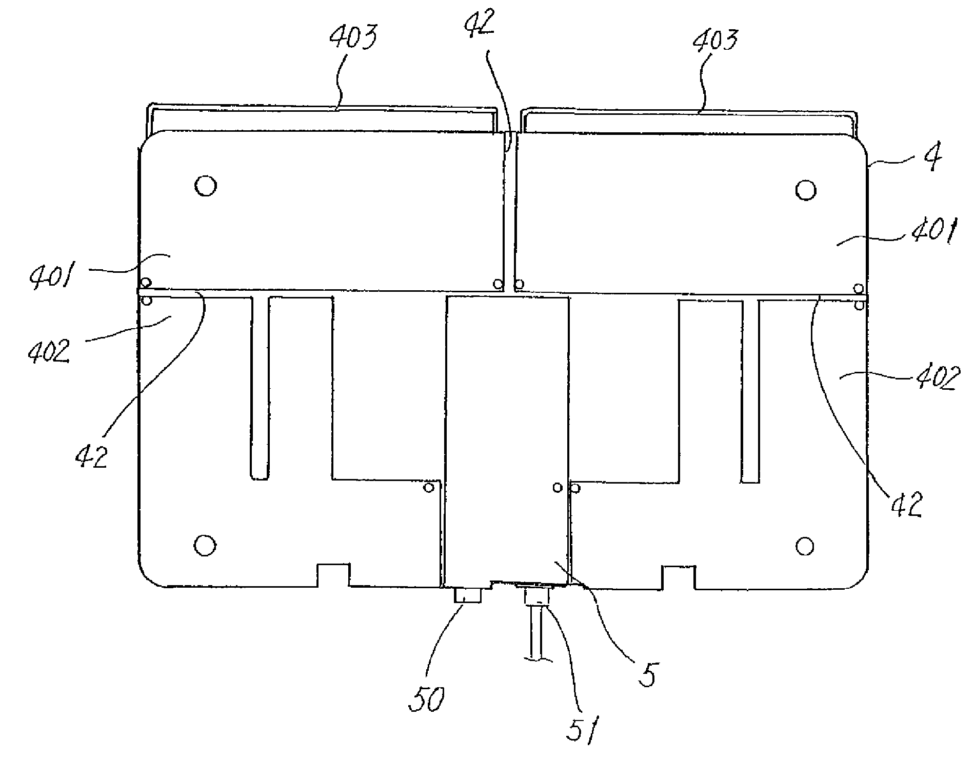
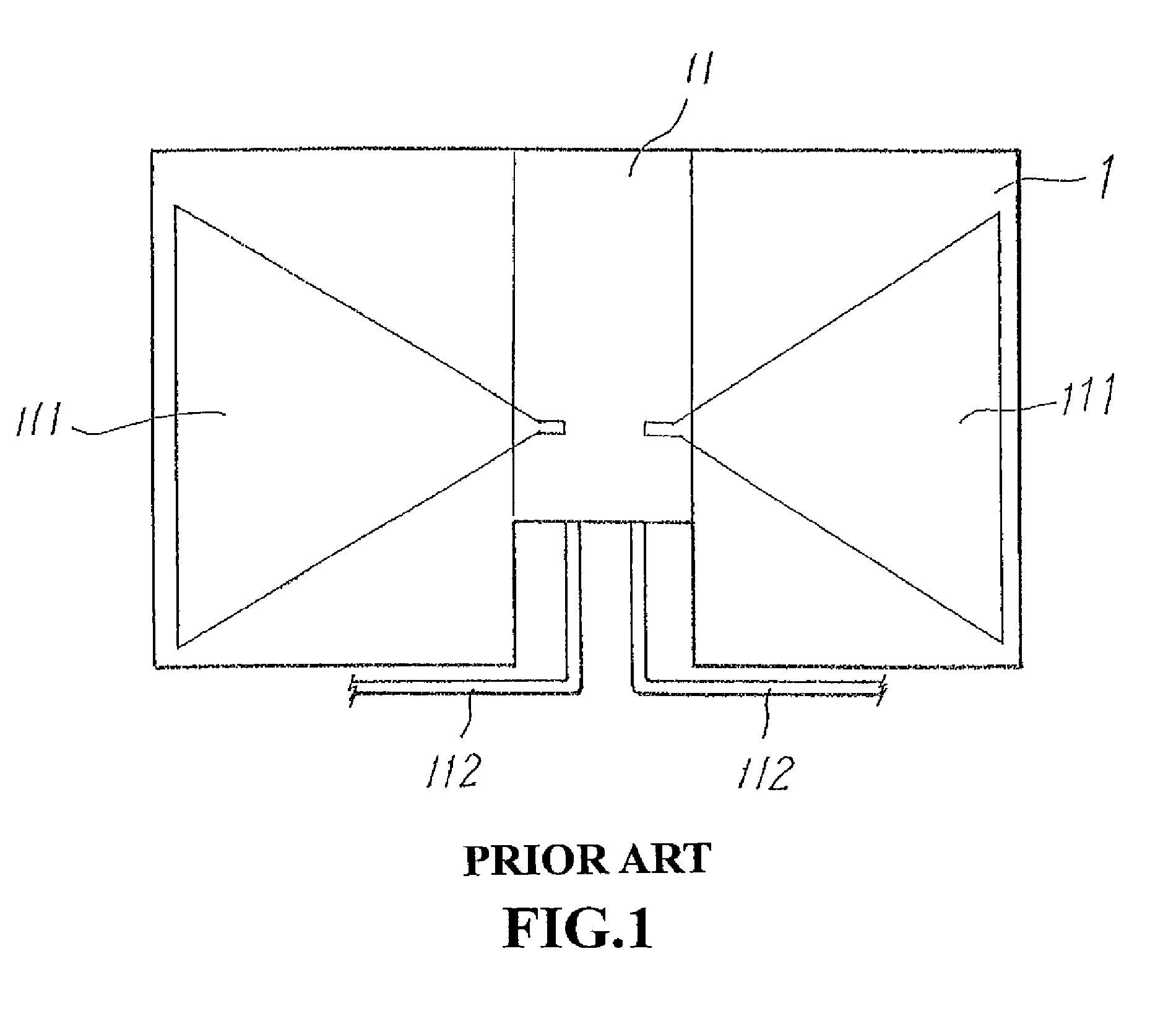
[0015]As illustrated in FIG. 4, a panel antenna according to an embodiment of the present invention has a slim box body 3 within which a circuit board 4 (as shown in FIG. 5) is housed. Unlike the conventional antenna which has to be oriented to aim at the broadcast signal source, the panel antenna of the present invention could be laid on a table top or hung on a wall surface. The box body 3 is composed of a top piece 32 and a bottom piece 31, which are both of a slim shape. The box body 3 therefore...


PUM


Abstract

A multi-directional panel antenna is provided for the reception of TV broadcast VHF and UHF signals. The panel antenna's circuit board has its current path substantially covers the surface of the circuit board so as to produce multi-directional reception patterns. An iron-core winding is configured at a feed-in terminal of the panel antenna for impedance matching and signal concentration. The panel antenna also uses air to reduce dielectric loss. A MMIC signal amplification device is provided for enhanced gain. Ceramic capacitors are provided to increase the reception wavelength of the panel antenna so that it falls within a lower section of the VHF band.

Description

TECHNICAL FIELD OF THE INVENTION [0001]The present invention generally relates to panel antennas, and more particularly to a panel antenna where its current path covers its circuit board so as to produce multi-directional reception pattern, to increase the signal reception wavelength, and to increase the effective signal reception area.DESCRIPTION OF THE PRIOR ART [0002]For receiving broadcast television (TV) programs, an outdoor or indoor antenna is a required device. For a conventional indoor antenna, as illustrated in FIG. 1, mainly contains a circuit board 1 having a circuit region 11 in a middle area and reception plates 111 at the lateral sides of the circuit region 1. Both the circuit region 11 and the reception plates 111 are printed on a major side of the circuit board 1. The reception plates 111 are for receiving UHF signals and, for VHF signals, copper strips 112 are provided and connected to the circuit region 11. As described, the conventional antenna has a very simple ...

Claims


Application Information

Patent Timeline
IPC IPC(8): H01Q9/04H01Q1/50
CPCH01Q1/007H01Q21/30H01Q9/285
Inventor CHANG, MING-WEN
Owner SAN WEN H K INT
Why Eureka
Try Eureka