Piezoelectric transducers

a technology of piezoelectric transducers and transducers, applied in piezoelectric/electrostrictive/magnetostrictive devices, mechanical vibration separation, instruments, etc., can solve problems such as complex engineering solutions that may be required to effectively prevent overheating, sensitivity and bandwidth of transducers are negatively impacted, and the stability of piezoelectric properties decreases steadily. , to achieve the effect of improving the resistivity and significantly improving the resistivity

Active Publication Date: 2018-01-18
IONIX ADVANCED TECH
View PDF5 Cites 5 Cited by
  • Summary
  • Abstract
  • Description
  • Claims
  • Application Information

AI Technical Summary

Benefits of technology

[0081]In one embodiment, the B-site metal dopant has a mixed valency. Substituting a mixed valency metal dopant onto a B-site may improve the resistivity significantly.
[0082]In one embodimen...

Problems solved by technology

Principally however, although PZT is effectively exploited in a wide range of markets it is fundamentally limited to applications below ˜200° C., above which the stability of its piezoelectric properties decrease steadily.
However, the sensitivity and bandwidth of the transducer is negatively impacted.
However, complicated engineering solutions may be required to effectively prevent overheating in this manner.
A further possibility is to simply accept that the materials will have a short lifespan in the high temperatur...

Method used


Image

  • Piezoelectric transducers
  • Piezoelectric transducers
  • Piezoelectric transducers

Examples


Embodiment Construction

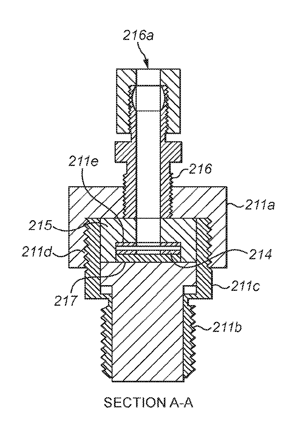
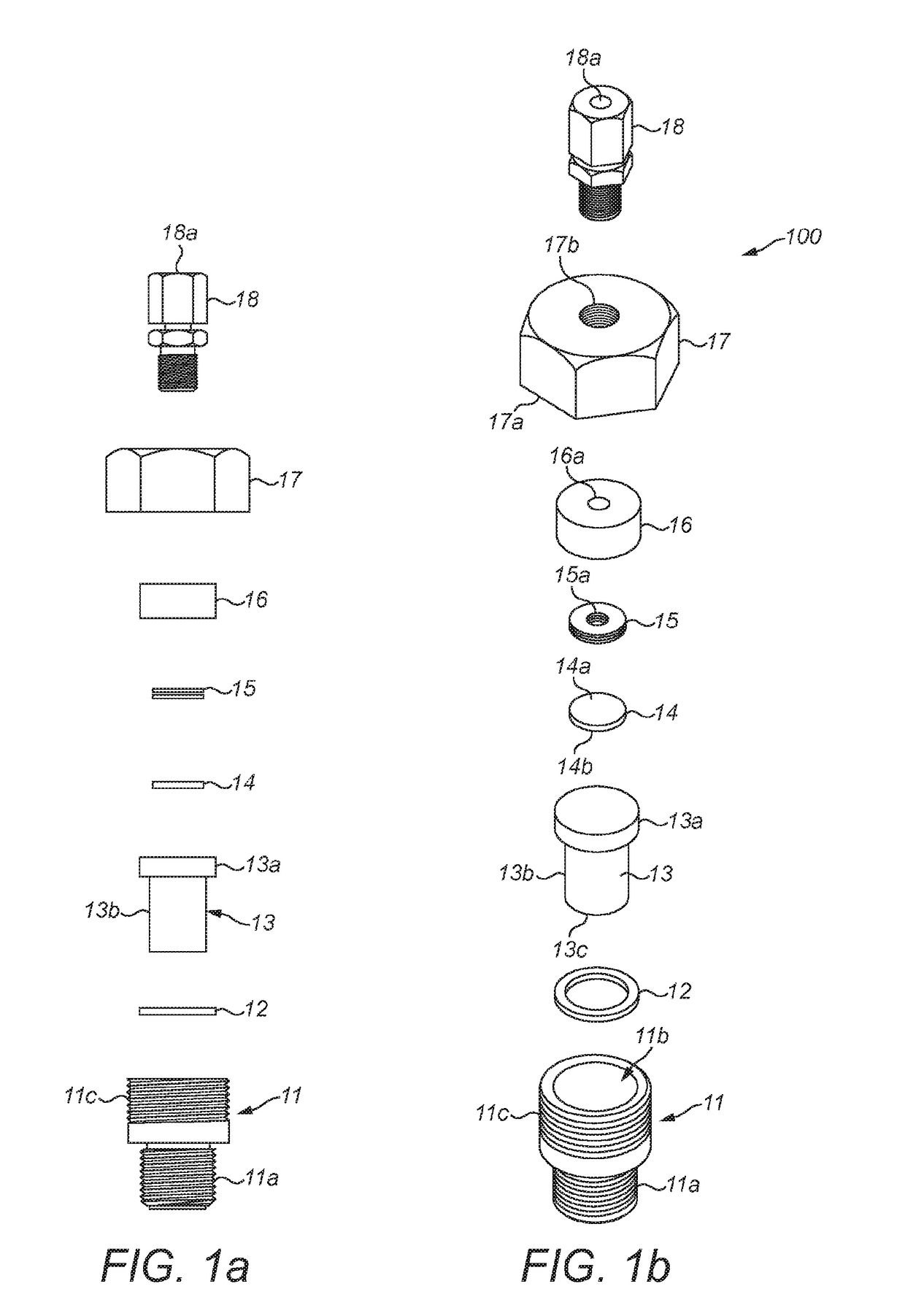
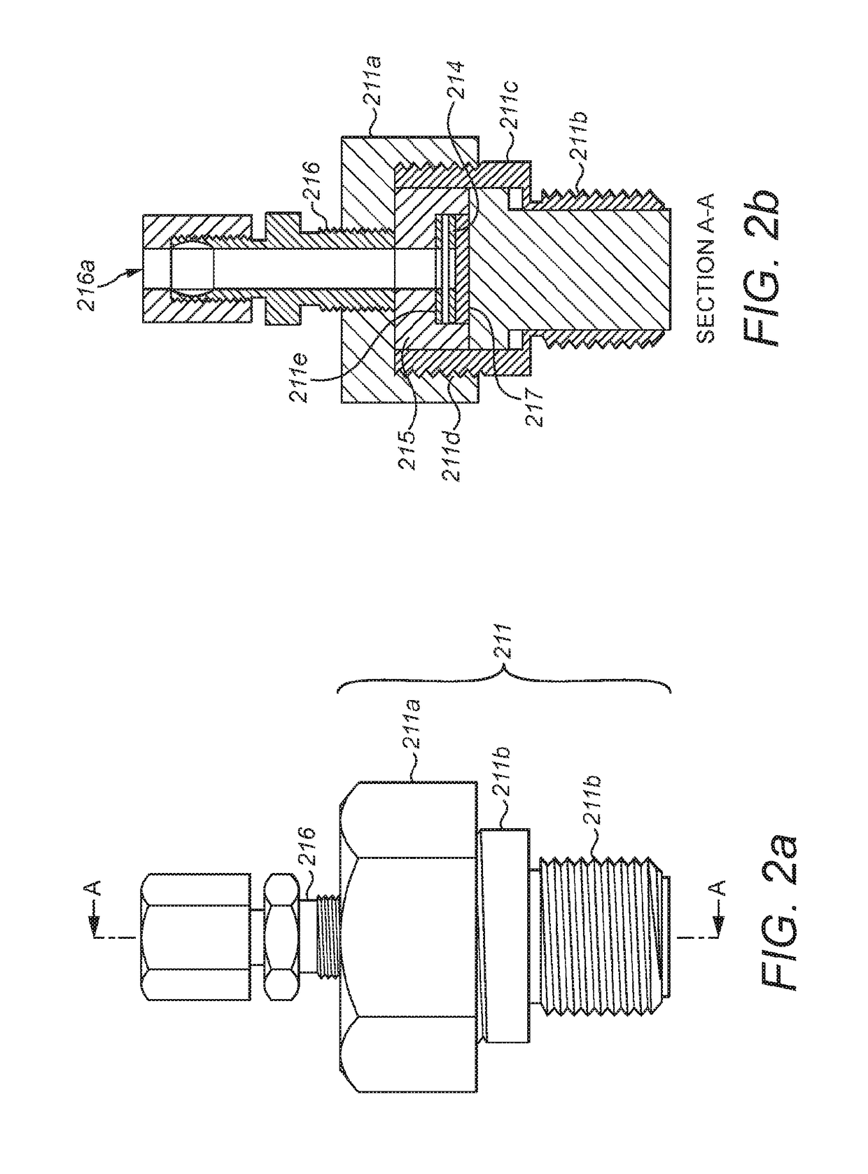
[0150]FIG. 1 shows an exploded view of a piezoelectric transducer device 100 in accordance with a first example embodiment of the disclosure. The piezoelectric transducer device 100 is configured to sense vibrations in a high temperature environment.

[0151]The transducer 100 comprises a housing 11, a washer 12, an effector 13, a piezoelectric element 14, an electrode plate 15, an isolator 16 and a cap 17.

[0152]The housing 11 retains the other elements of the transducer 100 whilst in use. In one example, the housing 11 is manufactured from stainless steel. The stainless steel may particularly be type 304 or 316 stainless steel or alternatively titanium or a nickel alloy.

[0153]The housing 11 comprises, for example, a threaded portion 11a which facilitates, for example, mounting to a pipe containing high temperature fluids when in use. Advantageously, the dimensions of the housing 11 are such that the assembled transducer 100 can be inserted into standard pipe clamps or mountings, or a ...


PUM


Abstract

A piezoelectric transducer comprises a piezoelectric element operable to transduce mechanical movement of the piezoelectric element to an electrical signal and to transduce an electrical signal in the piezoelectric element to a mechanical movement thereof, wherein the piezoelectric transducer is operable to transduce above a temperature of 200° C.

Description

CROSS-REFERENCE TO RELATED APPLICATIONS[0001]This application is a national stage of, and claims priority to, Patent Cooperation Treaty Application No. PCT / GB2016 / 050270 filed on Feb. 5, 2016, which claims priority to Great Britain Application No. GB1501923.5 filed on Feb. 5, 2015 both of which are hereby incorporated by reference in their entirety.FIELD OF THE DISCLOSURE[0002]This disclosure relates to piezoelectric transducers and to a method of manufacturing piezoelectric transducers, particularly, but not limited to, piezoelectric transducers with an ability to operate effectively at temperatures above at least 200° C., or in other extreme environments such as high pressure, high stress or irradiation.BACKGROUND OF THE DISCLOSURE[0003]Piezoelectric materials exhibit an electro-mechanical coupling, allowing them to develop an electric charge proportional to an applied mechanical stress in a direct mode. Alternatively, in a converse mode, they can generate a strain from the applic...

Claims


Application Information

Patent Timeline
IPC IPC(8): B06B1/06G01H11/08H01L41/187
CPCB06B1/0685B06B1/0644B06B1/0622H01L41/1876G01H11/08B06B1/0681H10N30/1071H10N30/853H10N30/8554
Inventor STEVENSON, TIMOTHY JAMESCOMYN, TIMOTHY PAUL ALISTAIR
Owner IONIX ADVANCED TECH
Why Eureka
Try Eureka