Treatment system and method for reducing dielectric loss value of transformer oil

A transformer oil and treatment method technology, which is applied in the field of transformer oil, can solve the problems of increased dielectric loss value of oil, pollution hiding places, not in place, such as not rinsed with water after pickling, etc., so as to reduce dielectric loss value and improve The effect of adsorption capacity

Active Publication Date: 2014-03-19
ZHONGSHAN KAIXUAN VACUUM SCI & TECH CO LTD +1
View PDF5 Cites 5 Cited by
  • Summary
  • Abstract
  • Description
  • Claims
  • Application Information

AI Technical Summary

Problems solved by technology

However, a simple oil change cannot "flush" thoroughly. After the oil change, the dielectric loss of the transformer oil will gradually increase or even exceed the qualified value.
In addition, the cost of oil change is high, which is not conducive to energy saving and environmental protection
[0004] Aiming at the problem of increased dielectric loss of transformer oil in the oil pipeline, we have come to the following conclusions after analyzing the oil pipeline: 1. The pipeline is not clean enough, such as not rinsed with water after pickling, or not dried in time after washing and then painted Transformer oil (before the two pipes are butt welded), resulting in the generation of metal oxides
2. When the pipe is welded butt welded, the incision is uneven or there is no chamfer. After welding, the internal weld seam of the pipe is not smooth, and pits or dents appear, resulting in the hiding point of pollutants.
3. The direction or theoretical pipe diameter of the pipeline is unreasonable. During the flow of transformer oil, pollutants cannot be taken away due to unreasonable design (for example, the pipe climbs too high), or the pipe diameter is too large, resulting in too slow flow rate, resulting in oil flow. Insufficient flushing force on the inner wall of the pipe, so that pollutants (such as acidic oxidation products, a small amount of microorganisms, metal oxides, colloidal insoluble substances, etc.) that cause the increase in oil dielectric loss remain in the pipe

Method used


Image

  • Treatment system and method for reducing dielectric loss value of transformer oil

Examples


Embodiment Construction

[0025] Typical embodiments embodying the features and advantages of the present invention will be described in detail in the following description. It should be understood that the present invention is capable of various changes in different embodiments without departing from the scope of the present invention, and that the description and drawings therein are illustrative in nature and not limiting. this invention.

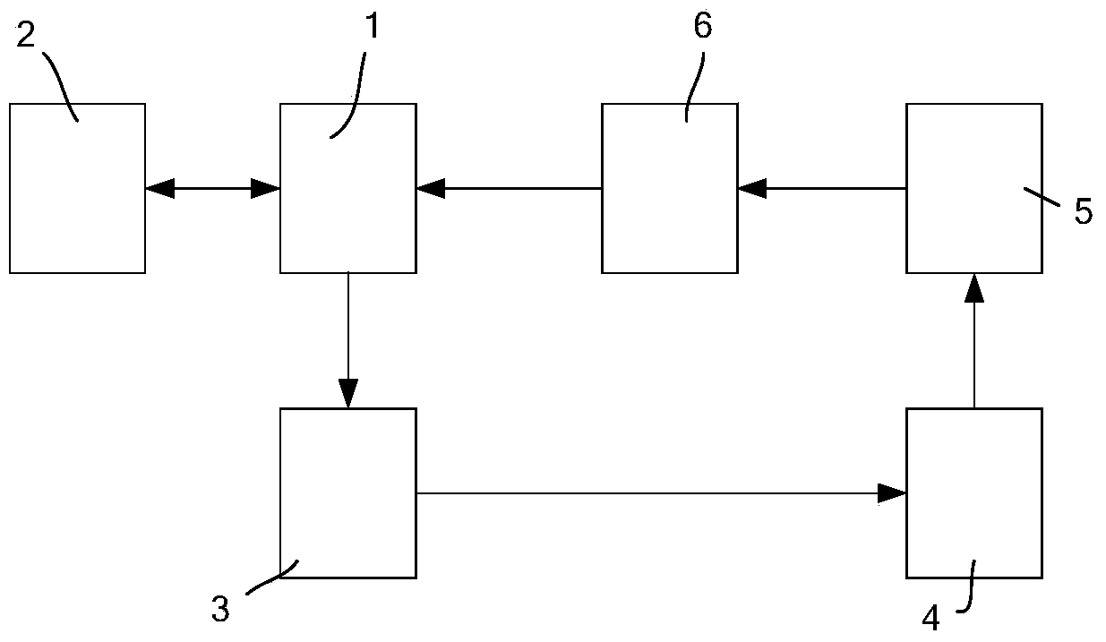
[0026] The structure of the processing system for reducing the dielectric loss value of transformer oil of the present invention is as follows: figure 1 As shown, it includes a clean oil tank 1, a vacuum oil filter 2, an oil pump 3, a heater 4, an oil damage treatment tank 5, and a filter 6. The two-way communication between the clean oil tank 1 and the vacuum oil filter 2, the clean oil Tank 1, oil pump 3, heater 4, oil damage treatment tank 5, and filter 6 are connected in one direction through pipelines in sequence to form a circular loop. On-off valves are a...


PUM


Abstract

The invention discloses a treatment system for reducing the dielectric loss value of transformer oil. The system comprises a vacuum oil filter, an oil purifying tank, an oil pump, a filter, a heater and an oil dielectric loss treatment tank which are communicated. The invention further provides a treatment method for reducing the dielectric loss value of the transformer oil. The method comprises the following steps: treating the transformer oil through the system; continuously circulating for 8 to 10 hours at each time; operating one time per day within 7 days before treating the transformer oil, then operating for one time every other 1 day, and operating for 3 to 4 times at intervals; after circulation treatment on the transformer oil is completed, adding an antioxidant into the transformer oil. According to the invention, dielectric loss pollutants in the transformer oil are absorbed by the oil dielectric loss treatment tank, and long-time and interval operation of the whole circulating system is performed, so that the dielectric loss pollutants in an oil conveying pipeline are adsorbed and removed, the dielectric loss value of the transformer oil is reduced, and the transformer oil is conveyed into the transformer from the oil purifying tank safely and reliably.

Description

technical field [0001] The invention relates to transformer oil, in particular to a treatment system and method for transformer oil with excess dielectric loss. Background technique [0002] Transformer oil dielectric loss factor (hereinafter referred to as dielectric loss) can reflect the insulation properties of transformer oil, reflect the aging degree of transformer oil under the action of electric field, oxidation and high temperature, and reflect the degree of pollution of polar impurities and charged colloids in oil . In the actual use process, we found that the reason why the dielectric loss of the transformer oil exceeds the standard is not only the internal pollution of the transformer itself, but also the pollution of the transformer oil from external pollutants, such as acid oxidation products, a small amount of microorganisms, metal oxides, etc. Pollutants such as colloidal insolubles and colloids have a great influence on the dielectric loss value of transform...

Claims


Application Information

Patent Timeline
Patent Type & Authority Applications(China)
IPC IPC(8): H01F27/14B01D36/00
Inventor 胡湘娥戴国良赵继荣范毓宏
Owner ZHONGSHAN KAIXUAN VACUUM SCI & TECH CO LTD
Why Eureka
Try Eureka