Hermetic compressor

a compressor and hermetic technology, applied in the direction of positive displacement liquid engines, piston pumps, liquid fuel engines, etc., can solve the problems of reducing a viscous resistance, achieve reliable feeding, reduce a viscous resistance, and suppress the amount of refrigerant

Active Publication Date: 2011-02-03
PANASONIC APPLIANCES REFRIGERATION DEVICES SINGAPORE
View PDF11 Cites 5 Cited by
  • Summary
  • Abstract
  • Description
  • Claims
  • Application Information

AI Technical Summary

Benefits of technology

[0036]In this hermetic compressor, the expanded clearance portion broadens the clearance between the piston and cylinder, resulting in reducing a viscous resistance. The sum of volumes of the first oil groove and the second oil groove enables reliable feeding of an amount of lubricating oil needed for reliably applying an oil seal to the broadening clearance between the piston and cylinder from the top dead point to the bottom dead point. In addition, the volume of the first oil groove not greater than that of the second oil groove suppresses amount of refrigerant gas flowing in from the compression chamber to the first oil groove during compression of refrigerant.

Problems solved by technology

In this hermetic compressor, the expanded clearance portion broadens the clearance between the piston and cylinder, resulting in reducing a viscous resistance.

Method used


Image

  • Hermetic compressor
  • Hermetic compressor
  • Hermetic compressor

Examples


example 1

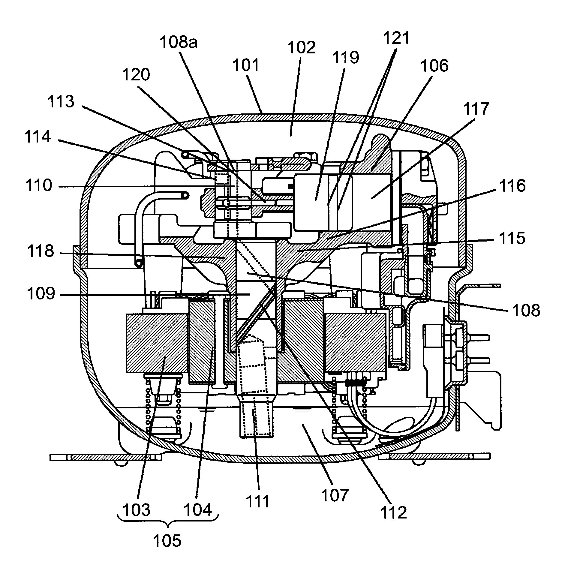
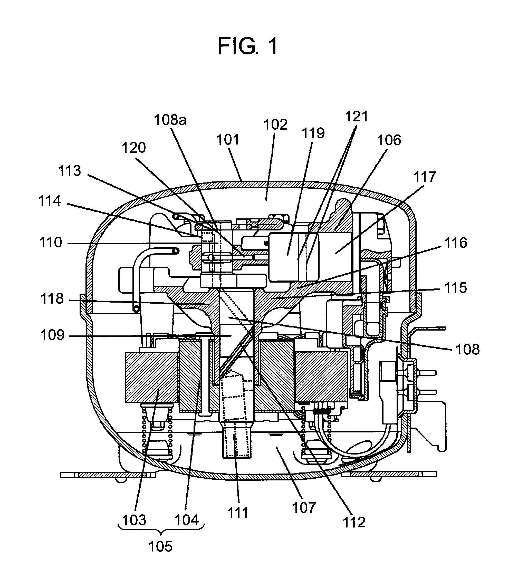
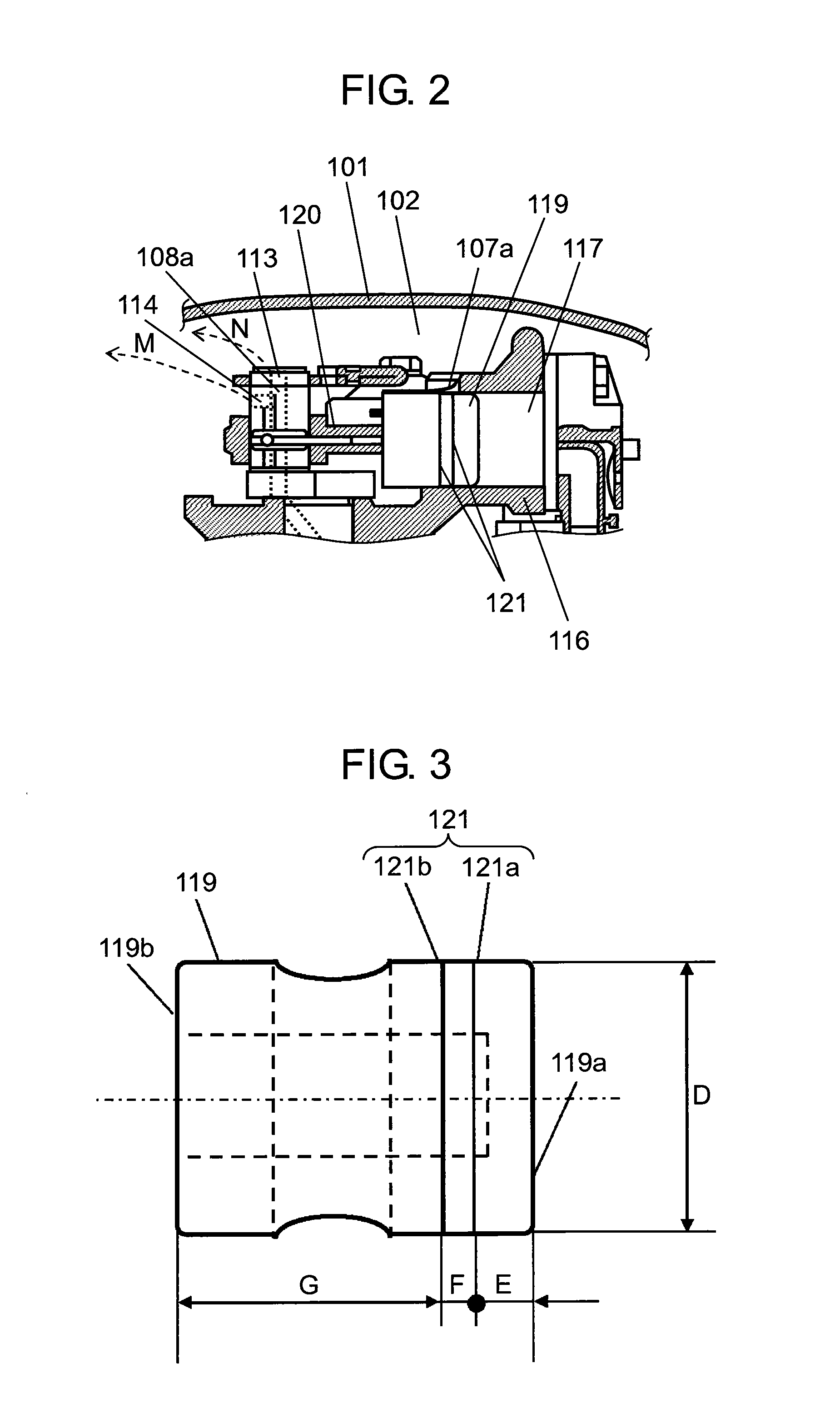
[0062]FIG. 1 is a vertical sectional view of a hermetic compressor in the first exemplary embodiment of the present invention. FIG. 2 is a sectional view of a key part around a piston of the hermetic compressor when the piston is at a bottom dead point. FIG. 3 is a magnified view of the piston of the hermetic compressor.

[0063]In FIGS. 1 to 3, the hermetic compressor includes electric-driving element 105 and compressing element 106 in closed-vessel space 102 inside closed vessel 101. Lubricating oil 107 is stored at the bottom of closed vessel 101.

[0064]Refrigerant in closed-vessel space 102 is R600a. R600a is hydrocarbon refrigerant, which is a typical natural refrigerant with a low global warming potential.

[0065]Electric-driving element 105 includes stator 103 and rotor 104 with a built-in permanent magnet (not illustrated). Compressing element 106 is driven by electric-driving element 105.

[0066]Compressing element 106 includes shaft 108, cylinder block 115, piston 119, and oiling ...

example 2

[0135]FIG. 9 is a sectional view of a hermetic compressor in the second exemplary embodiment of the present invention in a state that a piston is at a bottom dead point. FIG. 10 is a sectional view of the hermetic compressor in a state that the piston is at a top dead point.

[0136]The hermetic compressor includes electric-driving element 204 and compressing element 205 in closed-vessel 201. Lubricating oil 206 is stored at the bottom of closed vessel 201. Electric-driving element 204 includes stator 202 and rotor 203. Compressing element 205 is driven by electric-driving element 204. Compressing element 205 includes shaft 210, cylinder block 214, piston 223, and connecting device 226.

[0137]Shaft 210 includes main shaft 211 and eccentric shaft 212. Main shaft 211 is fixed to a shaft center of rotor 203. Eccentric shaft 212 is formed on one end of main shaft 211 in an eccentric manner so as to integrally move with main shaft 211. Electric-driving element 204 rotates main shaft 211.

[013...


PUM


Abstract

A hermetic compressor includes a closed vessel for storing lubricating oil, an electric-driving element, and a compressing element driven by the electric-driving element. The compressing element includes a cylinder block forming a compression chamber, a piton that reciprocates inside the compression chamber, and an oiling device for supplying the lubricating oil to an outer circumference of the piston. A first oil groove is concavely formed on the outer circumference of the piston, and a second oil groove is concavely formed on a side opposite to the compression chamber relative to the first oil groove. The second oil groove has a spatial volume same or greater than that of the first oil groove. An expanded clearance portion is provided such that a clearance between the piston and the cylindrical hole portion broadens from a top dead point to a bottom dead point.

Description

TECHNICAL FIELD[0001]The present invention relates to hermetic compressors.BACKGROUND ART[0002]Attention to energy conservation and resource conservation has been increasingly enhanced recently from the viewpoint of global environmental protection. For example, reduction of power consumption is strongly demanded than ever before in a hermetic compressor employed in a freezing system, such as a refrigerator-freezer for household use. Methods of reducing power consumption by increasing efficiency of the hermetic compressor are described next. One is to reduce a sliding loss at sliding portions, typically a clearance between a piston and cylinder, and a clearance between a main shaft and bearing. Another method is to reduce a loss of refrigerant leakage due to leakage of high-pressure refrigerant from a compression chamber to other part via the clearance between the piston and cylinder during compression of the refrigerant.[0003]A method of reducing sliding loss between the piston and ...

Claims


Application Information

Patent Timeline
Patent Type & Authority Applications(United States)
IPC IPC(8): F04B39/02F04B1/14
CPCF04B39/0005F04B39/023F04B39/122F04B35/04F04B53/18F16J1/08F04B53/008
Inventor INAGAKI, KONAKANO, AKIRAISHIDA, YOSHINORIMORITA, ICHIRO
Owner PANASONIC APPLIANCES REFRIGERATION DEVICES SINGAPORE
Why Eureka
Try Eureka