
Auxetic stents

a technology of stents and stents, applied in the field of stents, can solve problems such as the shrinkage of the cross section of the structur

Inactive Publication Date: 2011-02-03
MKP STRUCTURAL DESIGN ASSOCS
View PDF8 Cites 58 Cited by
  • Summary
  • Abstract
  • Description
  • Claims
  • Application Information

AI Technical Summary

Benefits of technology

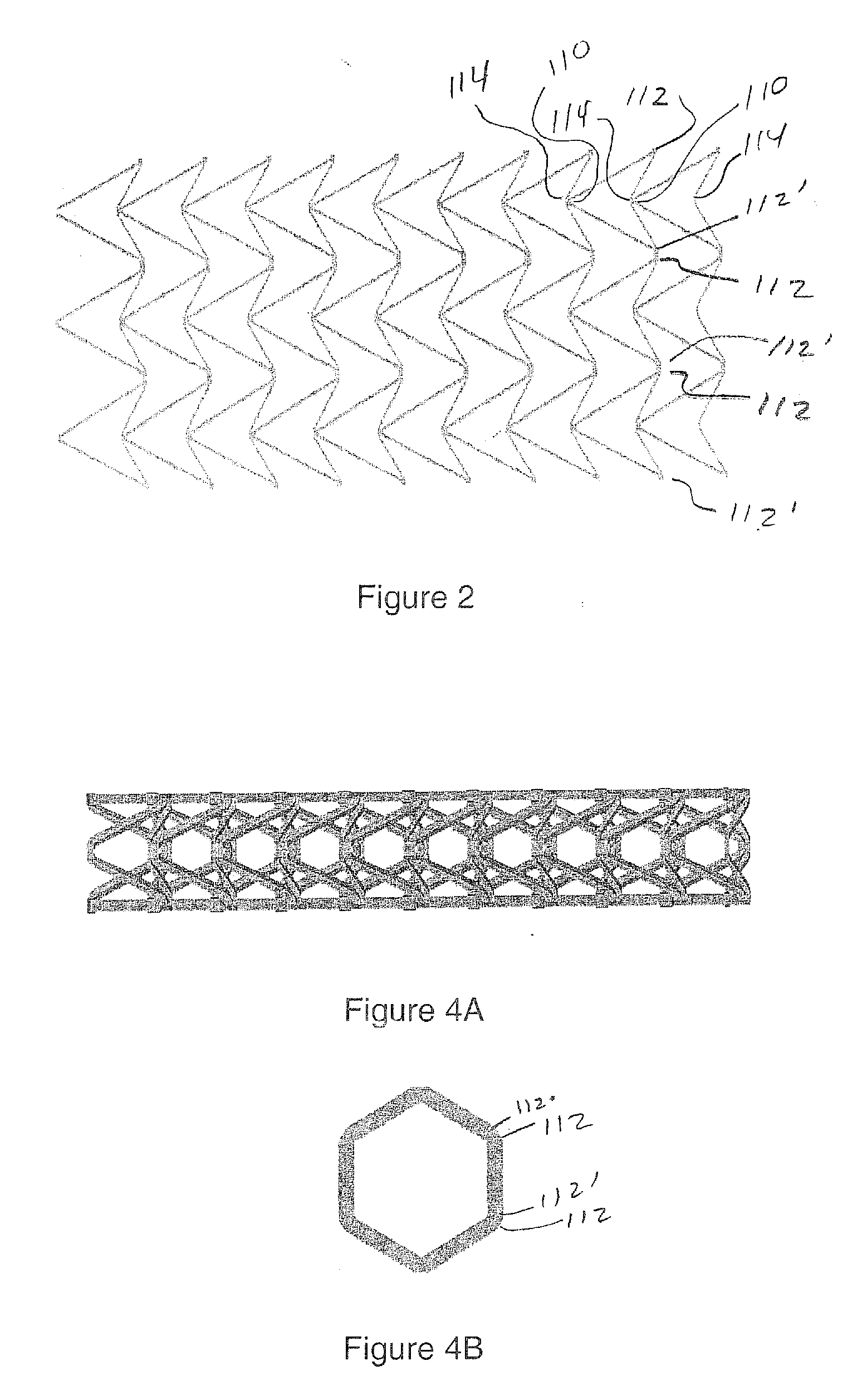
[0013]In certain preferred embodiments, the members define straight segments, and the cross section defines a regular polygon, such as a square, hexagon, octagon, decagon, dodecagon, or any higher-order polygon. Alternatively the members are curved, in which case the cross section of the tubular structure defines a circle. One advantage of the invention is that different types of unit cells may be combined to form hybrid structure. Such an approach may be particularly advantageous in terms of medical / surgical stent designs in that particular portions of the length of the stent such as the mid section may have a larger girth and / or be more resistant to externally applied pressure.
is that different types of unit cells may be combined to form hybrid structure. Such an approach may be particularly advantageous in terms of medical / surgical stent designs in that particular portions of the length of the stent such as the mid section may have a larger girth and / or be more resistant to externally applied pressure.

Problems solved by technology

Compression of the structure between the two ends thereof causes the cross section of the structure to shrink in size.

Method used


Image

  • Auxetic stents
  • Auxetic stents
  • Auxetic stents

Examples


Embodiment Construction

[0069]This invention is directed to negative Poisson's ratio (NPR) or auxetic structures and, in particular, to three-dimensional auxetic medical / surgical stents. As an introduction, co-pending U.S. patent application Ser. No. 12 / 267,867, describes a pyramid-shaped unit cell having four base points defining the corners of a square lying in a horizontal plane. Four “stuffer” members of equal length extend from a respective one of the base points to a fifth point spaced apart from the plane. Four “tendon” members of equal length, but shorter than the stuffers, extend from a respective one of the base points to a sixth point between the fifth point and the plane. In a preferred embodiment, a line drawn through the fifth and sixth points is normal to the plane.

[0070]The stuffer and tendon members may have a rectangular, round, or other cross section. The stuffers and the tendons may be of equal or unequal length, and may have equal or unequal cross sections. The stuffer and tendon membe...


PUM


Abstract

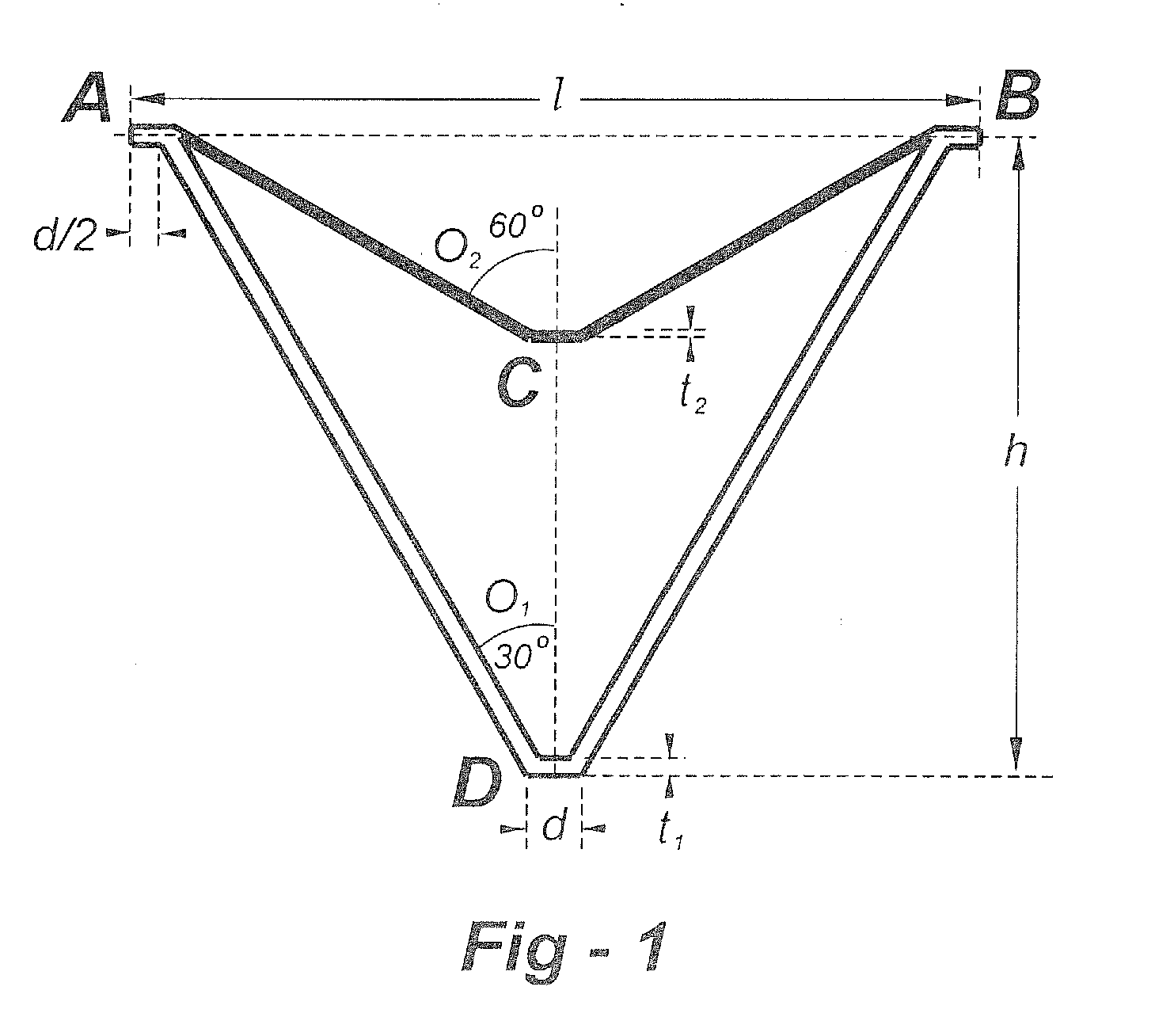
Stents of the type used to treat and prevent localized flow constriction in body vessels are based upon negative Poisson's ratio (NPR) structures. An auxetic stent constructed in accordance with this invention comprises a tubular structure having two ends defining a length with a central longitudinal axis and an axial view defining a cross section. The tubular structure is composed of a plurality of unit cells with two different configurations, called V-type and X-type. In V-type auxetic stents, each unit cell comprises a pair of side points A and B defining a width, a first pair of members interconnecting points A and B and intersecting at a point C forming a first V shape, and a second pair of members interconnecting points A and B and intersecting at a point D forming a second V shape. In X-type auxetic stents, each unit cell comprises eight points from A to H defining an outline of the unit cell. Eight straight or curved members interconnecting points A and B, B and C, C and D, C and E, E and F, F and G, G and H, G and A, respectively, forming the X-type unit cell. In both configurations, the unit cells are connected in rows and columns, such that compression of the structure between the two ends thereof causes the cross section of the structure to shrink in size. The auxetic structure configurations invented can also be used, with similar dimensions or significantly different dimensions, for other applications, such as in a nano-structural device, a tubal fastener design, or in an application associated with a large oil pipe or other pipelines.

Description

REFERENCE TO RELATED APPLICATION[0001]This application is a continuation-in-part of U.S. patent application Ser. No. 12 / 267,867, filed Nov. 10, 2008, the entire content of which is incorporated herein by reference.FIELD OF THE INVENTION[0002]This invention relates generally to medical / surgical stents and, in particular, to stents based upon negative Poisson's ratio (NPR) structures.BACKGROUND OF THE INVENTION[0003]Vascular stenting dates back to the late 1970s and the use of angioplasty balloons to treat vessel constrictions. Although arteries could be opened successfully using a balloon, in some cases the vessel would collapse after the balloon was deflated. Another problem has been restinosis or reblocking. Approximately 30 percent of all coronary arteries began to close up again after balloon angioplasty. Bypass and graft surgeries and miniaturized tools delivered via catheter were all used to find solutions.[0004]Stents were developed in the 1980s. A stent is a metal (or other m...

Claims


Application Information

Patent Timeline
Patent Type & Authority Applications(United States)
IPC IPC(8): A61F2/82A61F2/90
CPCA61F2/915A61F2002/91566A61F2230/0054A61F2230/0021A61F2230/0017
Inventor MA, ZHENG-DONGLIU, YUANYUAN
Owner MKP STRUCTURAL DESIGN ASSOCS
Learn More