
Harmonic Drive Camshaft Phaser with Bias Spring

a camshaft and bias spring technology, applied in the direction of couplings, machines/engines, gearing, etc., can solve the problems of phaser no, complexity of design and fabrication, and undesired bulkiness of the overall phaser package, and achieve the effect of easy assembly

Active Publication Date: 2011-02-10
DELPHI TECH IP LTD
View PDF6 Cites 35 Cited by
  • Summary
  • Abstract
  • Description
  • Claims
  • Application Information

AI Technical Summary

Benefits of technology

[0009]Briefly described, an eVCP camshaft phaser comprises a flat harmonic drive unit having a circular spline and a dynamic spline linked by a common flexspline within the circular and dynamic splines, and a single wave generator disposed within the flexspline. The circular spline is connectable to either of an engine crankshaft sprocket or an engine camshaft, the dynamic spline being connectable to the other thereof. The wave generator is driven selectively by an eMotor to cause the dynamic spline to rotate past the circular spline, thereby changing the phase ...

Problems solved by technology

A first drawback of this arrangement is that the overall phaser package is undesirably bulky in an axial direction and thus consumptive of precious space in an engine's allotted envelope in a vehicle.
A second drawback is that two complete wave generator units are required, resulting in complexity of design and cost of fabrication.
A third drawback is that the phaser has no means to move the driven unit and attached camshaft to a phase position with respect to the crankshaft that would allow the engine to start and / or run in case of drive motor power malfunction. eVCP have been put into production by two Japanese car manufacturers; interestingly, these devices have been limited to very low phase shift authority despite the trend in hydraulic variable cam phasers (hVCP) to have greater shift authority.
Thus, phase authority in production eVCPs to date has been undesirably limited to a low phase angle to avoid a stall or no-restart condition if the rotational position of the eVCP is far from an engine-operable position when it experiences eMotor or controller malfunction.

Method used


Image

  • Harmonic Drive Camshaft Phaser with Bias Spring
  • Harmonic Drive Camshaft Phaser with Bias Spring
  • Harmonic Drive Camshaft Phaser with Bias Spring

Examples


Embodiment Construction

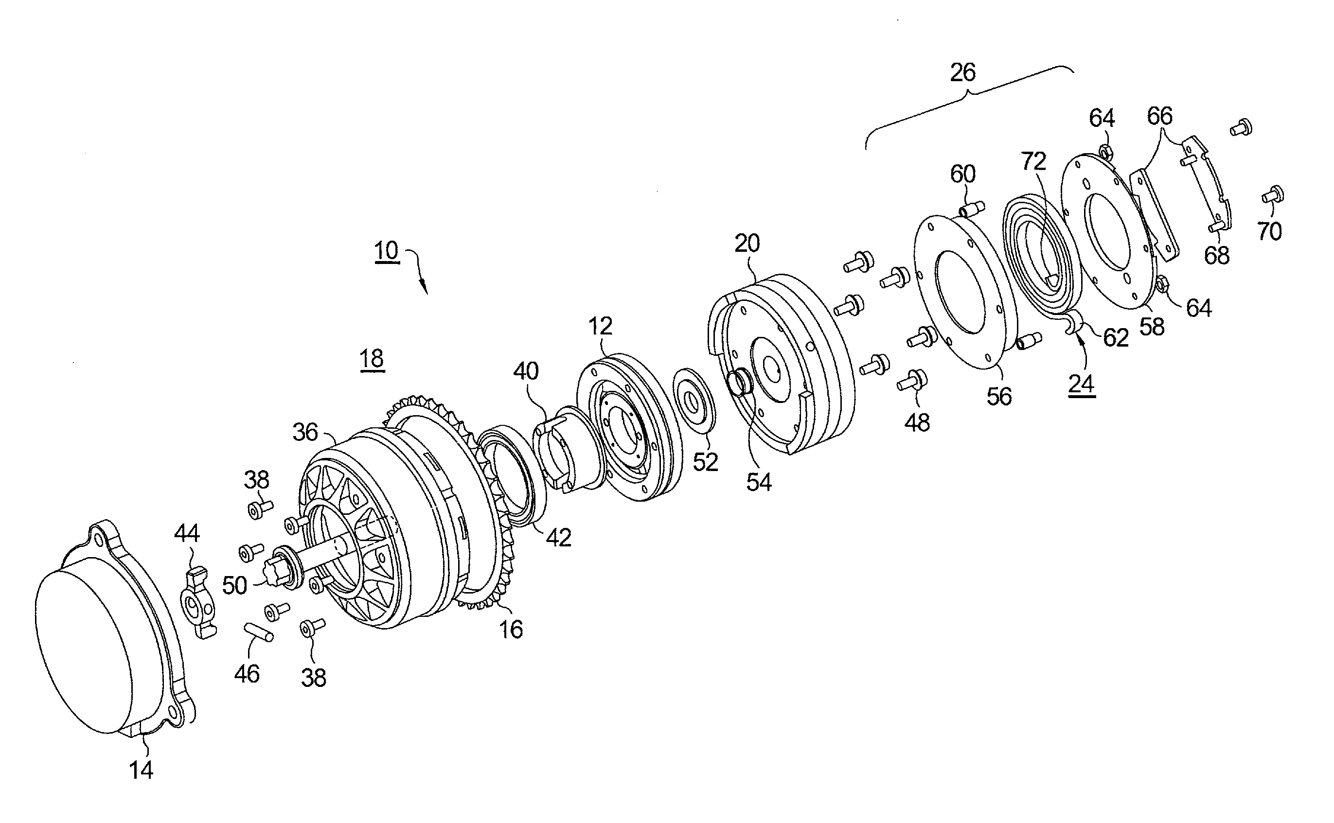
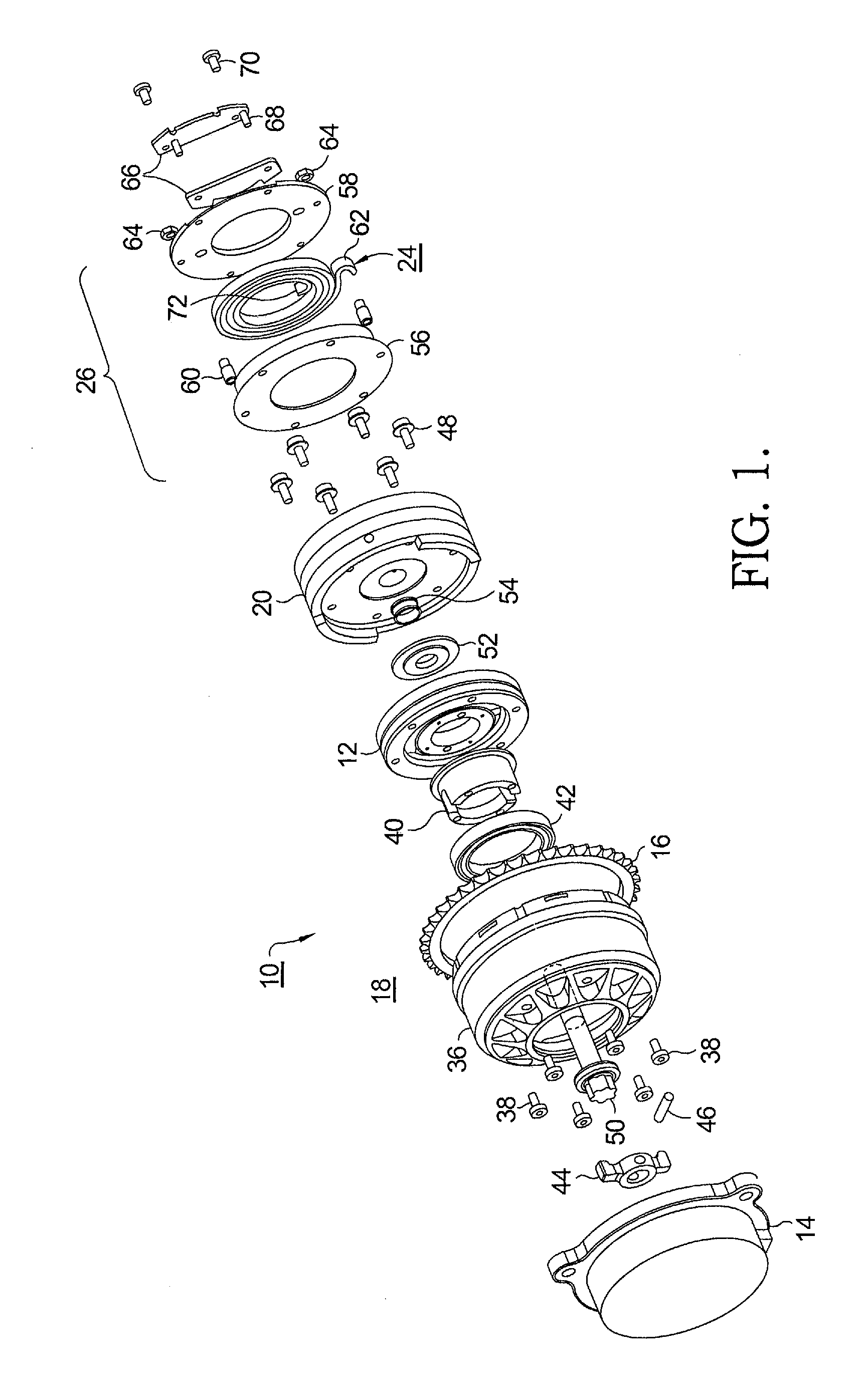
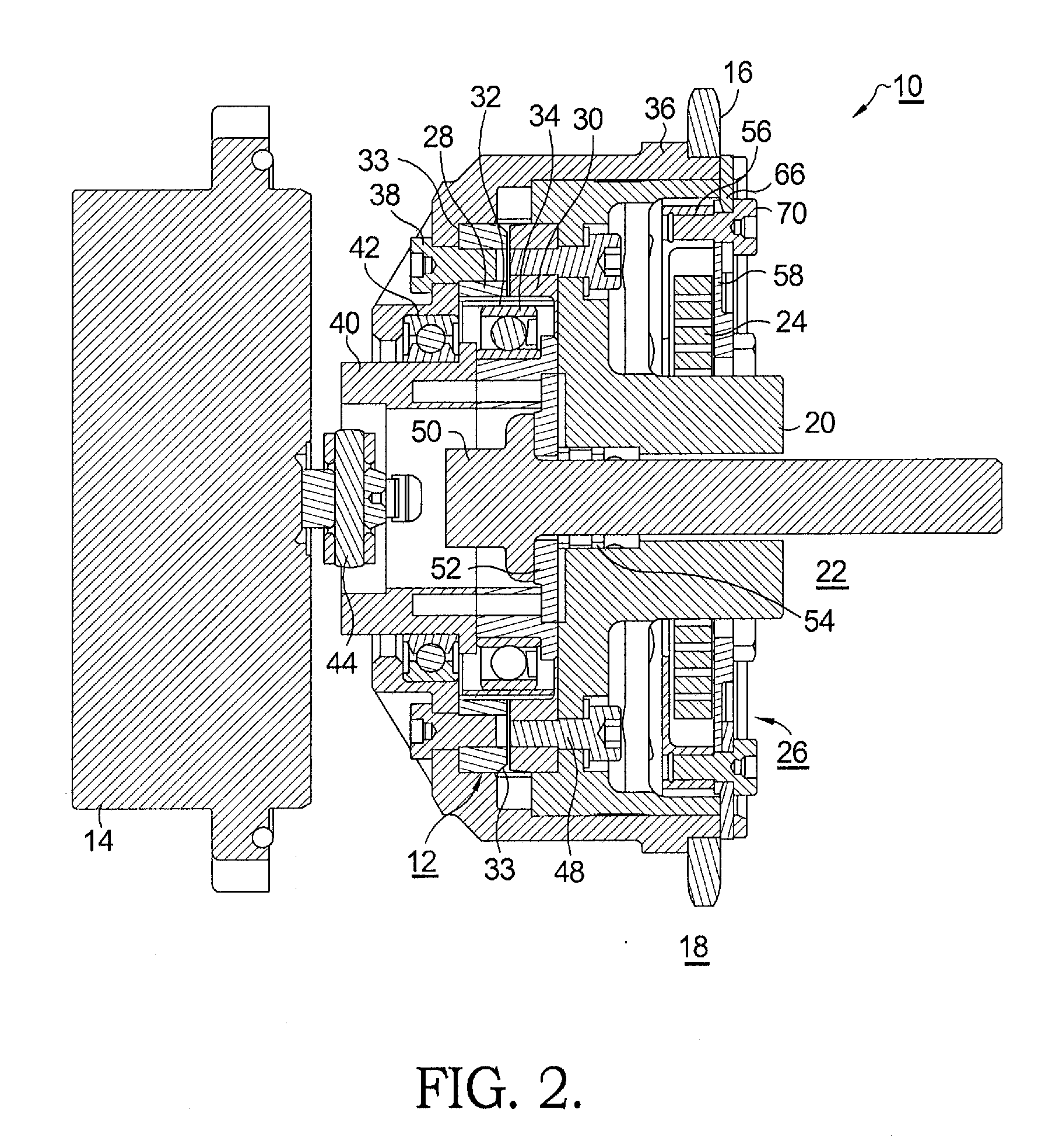
[0020]Referring to FIGS. 1 through 4, an eVCP 10 in accordance with the present invention comprises a flat harmonic gear drive unit 12; a rotational actuator 14 that may be a hydraulic motor but is preferably a DC electric motor (eMotor), operationally connected to harmonic gear drive unit 12; an input sprocket 16 operationally connected to harmonic gear drive unit 12 and drivable by a crankshaft of engine 18; an output hub 20 attached to harmonic gear drive unit 12 and mountable to an end of an engine camshaft 22; and a bias spring 24 operationally disposed between output hub 20 and input sprocket 16. Spring 24 may be a component of a spring cassette 26. eMotor 14 may be an axial-flux DC motor.

[0021]Harmonic gear drive unit 12 comprises an outer first spline 28 which may be either a circular spline or a dynamic spline as described below; an outer second spline 30 which is the opposite (dynamic or circular) of first spline 28 and is coaxially positioned adjacent first spline 28; a f...


PUM


Abstract

An eVCP camshaft phaser comprising a harmonic gear drive unit having a circular spline and a dynamic spline linked by a common flexspline, and a single wave generator disposed within the flexspline. The circular spline is connectable to either of a crankshaft-connectable sprocket or an engine camshaft, the dynamic spline being connectable to the other thereof. The wave generator is driven selectively by an eMotor to cause the dynamic spline to rotate past the circular spline, thereby changing the phase relationship between the crankshaft and the camshaft. A coaxial coil spring is connected to the sprocket and to the phaser hub and is positioned and tensioned to bias the phaser and camshaft to a stop position wherein the engine can run or be restarted after the eMotor is de-energized. Preferably, the spring comprises a spring cassette for easy assembly into the eVCP.

Description

TECHNICAL FIELD[0001]The present invention relates to camshaft phasers for varying the timing of combustion valves in internal combustion engines by varying the phase relationship between an engine's crankshaft and camshaft; more particularly, to oil-less camshaft phasers wherein a harmonic gear drive unit is controlled by an electric motor (eMotor) to vary the phase relationship, also referred to herein as an “electric variable cam phaser” (eVCP); and most particularly, to an eVCP including a bias spring to return the eVCP to a predetermined default phase position. In one aspect of the invention, the bias spring may be provided in a housing, in cassette form.BACKGROUND OF THE INVENTION[0002]Camshaft phasers (“cam phasers”) for varying the timing of combustion valves in an internal combustion engines are well known. A first element, known generally as a sprocket element, is driven by a chain, belt, or gearing from an engine's crankshaft. A second element, known generally as a camsha...

Claims


Application Information

Patent Timeline
IPC IPC(8): F01L1/34
CPCF01L1/344F01L1/352F16H49/001F01L2001/34483F01L2001/3521F01L2001/34463
Inventor DAVID, PASCALSTOLTZ-DOUCHET, SEBASTIENKIMUS, PIERREFOX, MICHAEL J.
Owner DELPHI TECH IP LTD
Learn More