Valve-controlled positive-displacement machine

a positive displacement machine and valve control technology, applied in the direction of valve details, valve arrangement, pump control, etc., can solve the problems of pressure surge (pulsation), all the cylinder-piston units are always active, and the alternation of active and inactive cylinder-piston units, so as to reduce the pulsation of the positive displacement machine

Inactive Publication Date: 2011-02-10
ROBERT BOSCH GMBH
View PDF3 Cites 13 Cited by
  • Summary
  • Abstract
  • Description
  • Claims
  • Application Information

AI Technical Summary

Benefits of technology

[0008]By comparison, it is the object of the invention to create a valve-controlled hydrostatic positive-displacement machine (DDU) and a method for controlling it, in which the excitation to vibration of a connected hydraulic system (in the case of a pump) or a connected power takeoff shaft (in the case of a motor) by the pulsation of the positive-displacement machine can be reduced.

Problems solved by technology

A disadvantage of such hydrostatic positive-displacement machines is that all the cylinder-piston units are always active.
A disadvantage of such valve-controlled positive-displacement machines (DDUs) is the pressure surges (pulsation), which result from the alternation of active and inactive cylinder-piston units.
This pulsation, for instance in the case of a pump, can excite a hydraulic system connected to it to unwanted vibration, especially if the pulsation matches a resonant frequency of the system.

Method used


Image

  • Valve-controlled positive-displacement machine
  • Valve-controlled positive-displacement machine
  • Valve-controlled positive-displacement machine

Examples


Embodiment Construction

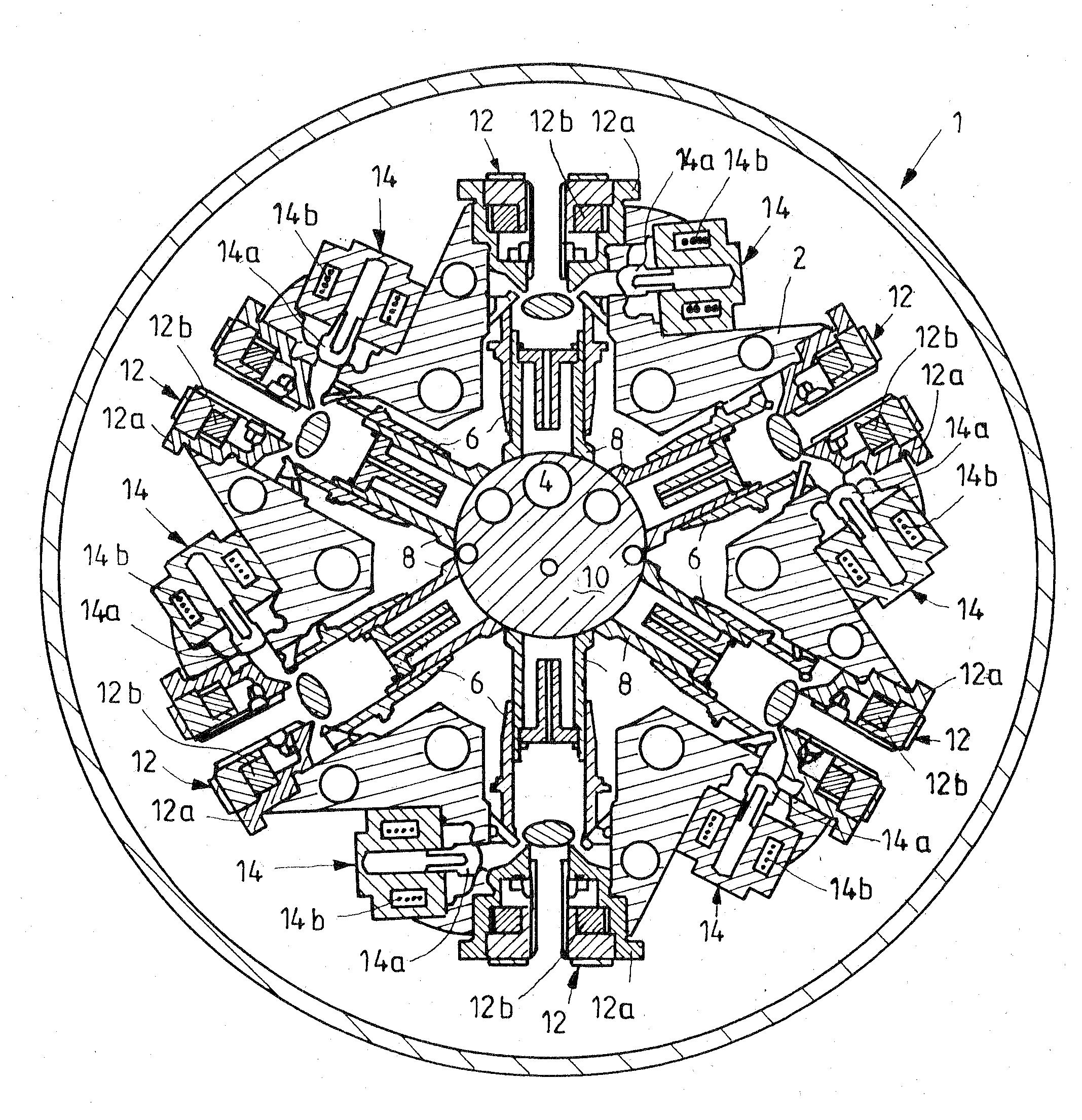
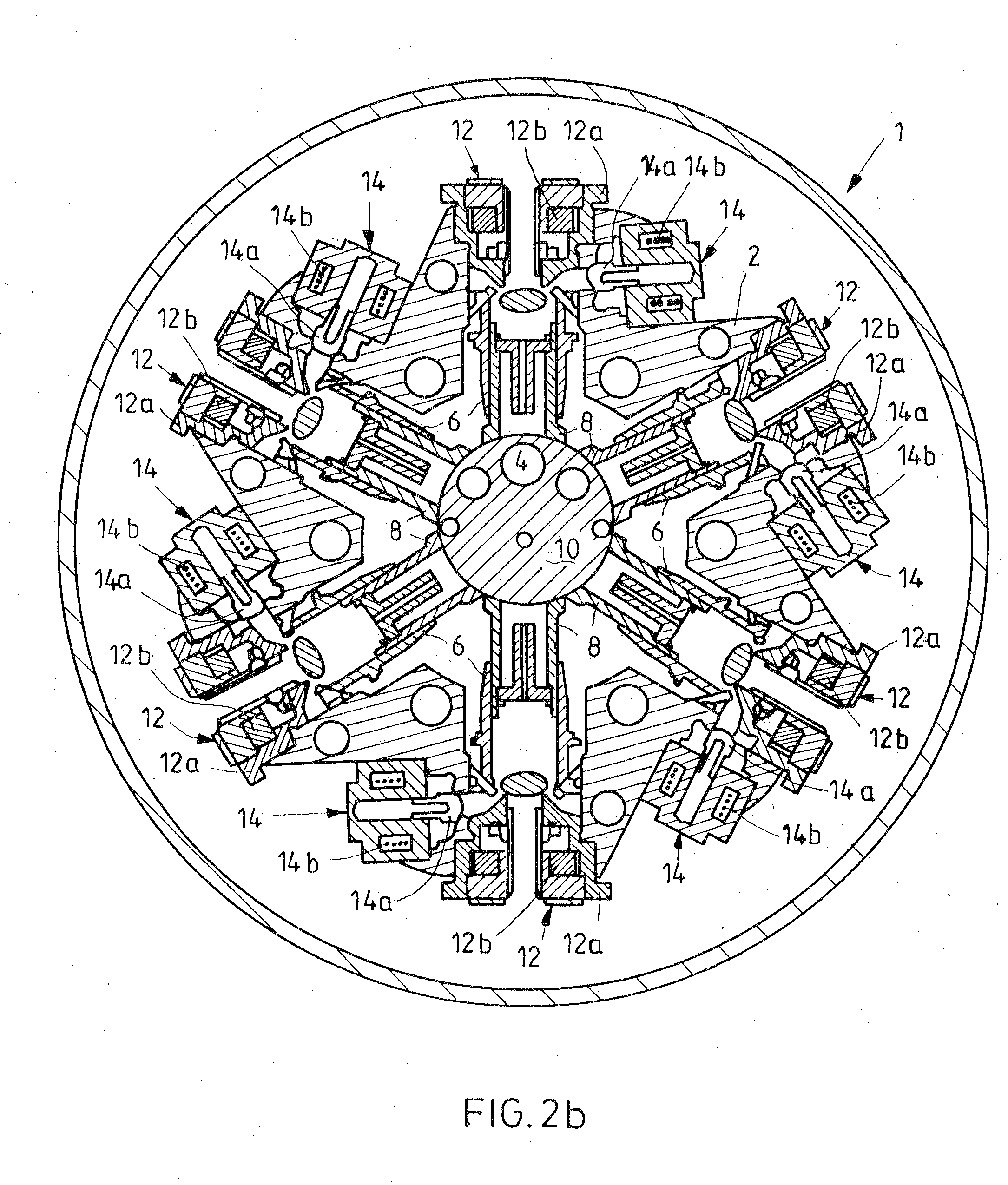
[0031]FIG. 1 shows one exemplary embodiment of a valve-controlled radial piston pump (Digital Displacement Unit) according to the invention in a sectional view. It has a housing 1, in which a stationary cylinder body 2 is received. Relative to an axis of rotation 4, six radial recesses are located in the cylinder body, with one cylinder-piston unit located in each recess. The six cylinder-piston units likewise extend approximately radially away from the axis of rotation 4. The bushlike cylinders 6, on their radially outer end portions, are secured pivotably to the cylinder body 2, and the pistons 8 are braced with their radially inner end portions on an eccentric element 10, or on its outer jacket face. The eccentric element 10 is supported rotatably about the axis of rotation 4 and is connected to a drive shaft (not shown) of the radial piston pump.

[0032]Each cylinder-piston unit 6, 8 is connected to a low-pressure connection (not shown) via a low-pressure valve 12 and to a high-pr...


PUM


Abstract

In a valve-controlled hydrostatic positive-displacement machine and a method for its control, the positive-displacement machine having a plurality of cylinder-piston units which are activated or deactivated via electrically or electro-hydraulically actuated low-pressure valves and via high-pressure valves for setting a delivery or absorption volume flow of the positive-displacement machine, if the volume flow is essentially unchanged, the activation and deactivation of the cylinder-piston units is effected in accordance with one of a plurality of activation patterns valid for the particular volume flow.

Description

BACKGROUND OF THE INVENTION[0001]The invention relates to a method for controlling a valve-controlled hydrostatic positive-displacement machine and to a valve-controlled hydrostatic positive-displacement machine.[0002]In conventional positive-displacement machines, which can be embodied as radial or axial piston machines, for instance, the control of the inflow and outflow of the individual cylinder-piston units is done mechanically. In the case of an axial piston pump, for example, two pressure crescents are used, by way of which the connections with the high-pressure side and the low-pressure side open during a certain range of the orbit and thus during a certain stroke segment of the cylinder-piston units.[0003]In radial piston pumps, one high-pressure valve and one low-pressure valve per cylinder-piston unit are provided, and the valves are mechanically controlled. The high-pressure valve of each unit for instance always opens if a certain built-up pressure in the applicable cyl...

Claims


Application Information

Patent Timeline
Patent Type & Authority Applications(United States)
IPC IPC(8): F16K31/12F16K31/02
CPCF04B49/06F04B49/03
Inventor LOPEZ PAMPLONA, ALEJANDROBEUTER, BJOERN
Owner ROBERT BOSCH GMBH
Why Eureka
Try Eureka