Magnetic sensor stack body, method of forming the same, film formation control program, and recording medium

a stack body and magnetic sensor technology, applied in the field of magnetic fields, can solve problems such as noise in a read head, and achieve the effect of increasing the magnetic anisotropy of the magnetic layer

Active Publication Date: 2011-02-10
CANON ANELVA CORP
View PDF21 Cites 118 Cited by
  • Summary
  • Abstract
  • Description
  • Claims
  • Application Information

AI Technical Summary

Benefits of technology

[0030]According to the first aspect of the invention, a ferromagnetic stack is provided on a part of an antiferromagnetic layer, width of an uppermost face of the ferromagnetic stack along a direction in which junction wall faces of a magnetoresistive element are opposed is smaller than width of an uppermost face of the antiferromagnetic layer in the same direction, and crystal c-axes in magnetic layers near the junction wall faces are in a direction along the ABS in a plane. Therefore, since the crystal c-axes in the magnetic layer near the junction wall face are oriented almost perpendicular to the junction wall face, an excellent effect such that the magnetic fluxes can be condensed to the magnetoresistive element is produced.
[0031]According to the second aspect of the invention, by optimizing the material, thickness, and sputter incident angle of an underlayer, the magnetic anisotropy of the magnetic layer can be increased. Therefore, the crystal c-axes in the magnetic layer near the junction wall face are oriented along the ABS, that is, in a direction almost perpendicular to the junction wall face. An excellent effect such that the magnetic fluxes can be condensed to the magnetoresistive element is produced.

Problems solved by technology

Nonuniformity of magnetic fields causes noise in a read head.

Method used


Image

  • Magnetic sensor stack body, method of forming the same, film formation control program, and recording medium
  • Magnetic sensor stack body, method of forming the same, film formation control program, and recording medium
  • Magnetic sensor stack body, method of forming the same, film formation control program, and recording medium

Examples


first embodiment

[Structure of Magnetic Sensor Stack Body]

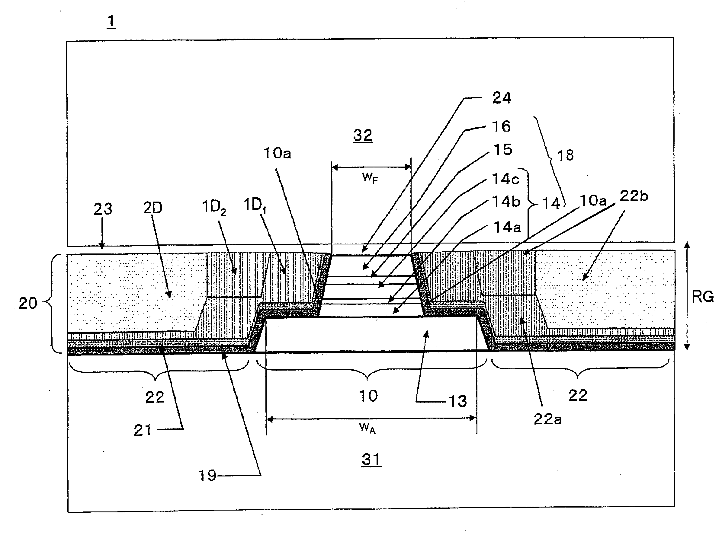
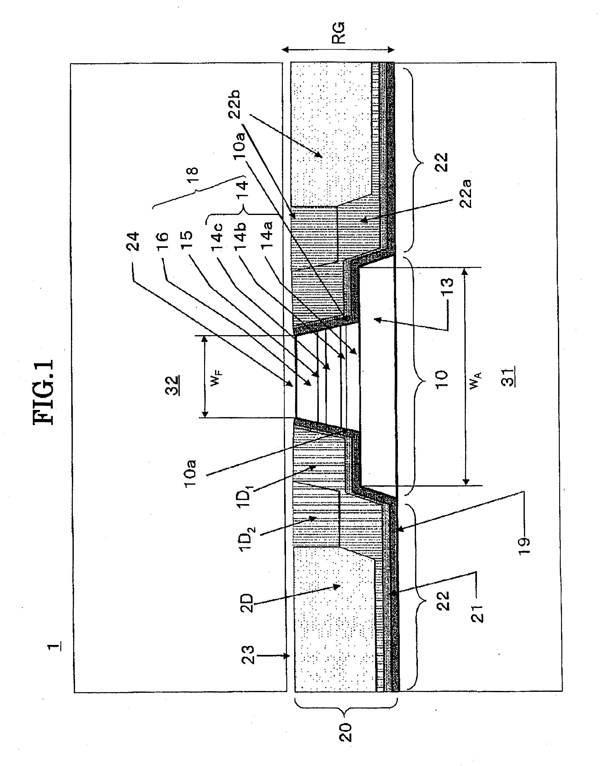
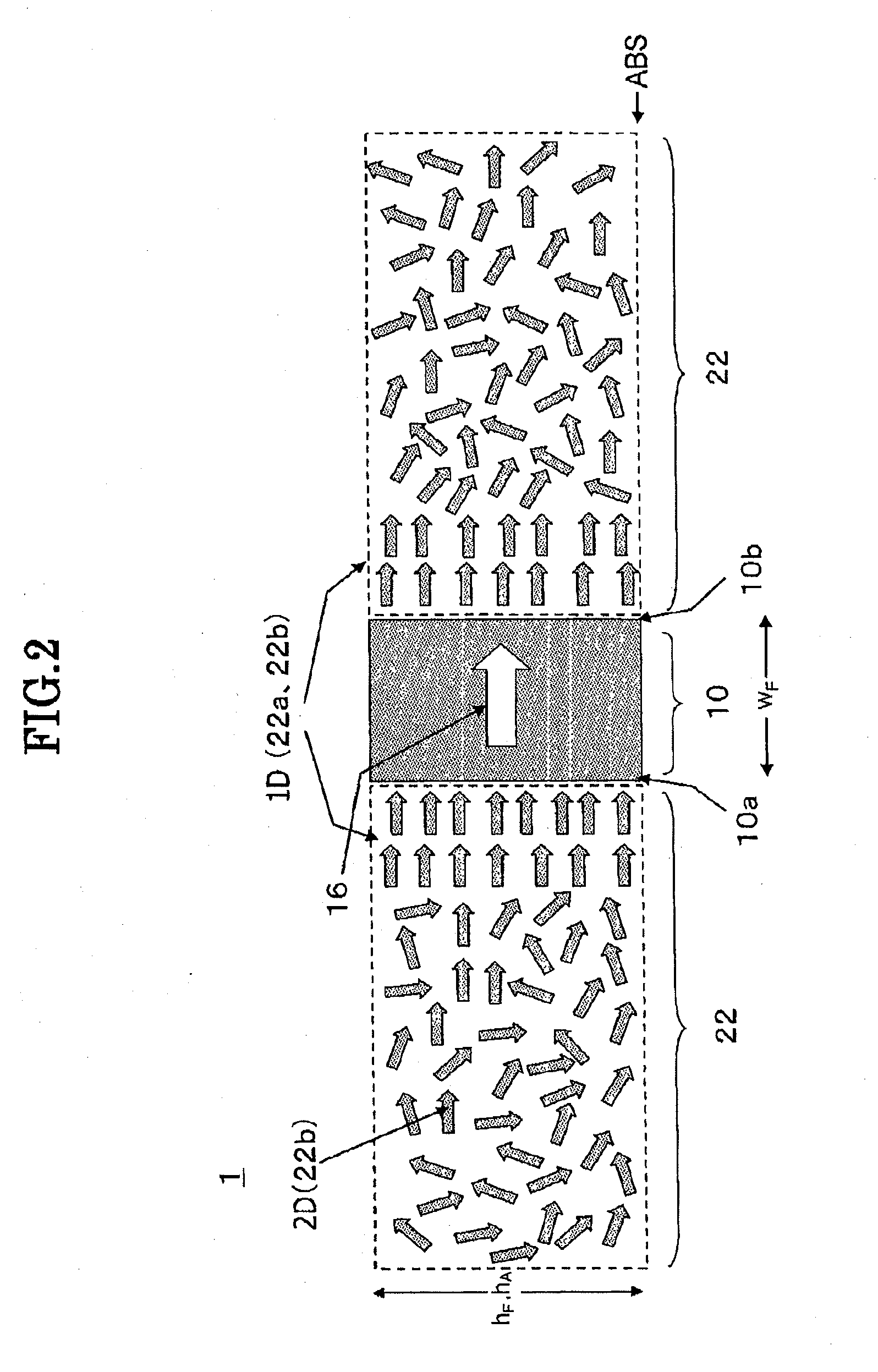
[0060]First, with reference to FIGS. 1 and 2, the structure of a magnetic sensor stack body having a magnetoresistive element will be described. FIG. 1 is an outline drawing schematically showing a magnetic sensor stack body according to the embodiment. FIG. 2 is an outline drawing showing a profile perpendicular to a stack direction of the magnetic sensor stack body according to the embodiment.

[0061]As shown in FIG. 1, a magnetic sensor stack body 1 according to the embodiment has, in an almost center on a substrate 31, a magnetoresistive element (reader stack) 10 made of a plurality of stack films having different compositions and having the magnetoresistive effect in which an electric resistance value fluctuates when a magnetic field is applied. The magnetic sensor stack body 1 also has, in field regions 22 on the sides of two opposed junction wall faces (surfaces) 10a and 10b of the reader stack 10, hard bias stack bodies 20 which can app...

second embodiment

[0129]Next, with reference to FIGS. 10 and 11, a magnetic sensor stack body 100 of a second embodiment and a method of farming the same will be described. FIG. 10 is an outline drawing of procedure corresponding to FIGS. 5B and 5C in the first embodiment. FIG. 11 is an outline drawing showing a complete form of a magnetic sensor stack body according to the second embodiment. The same reference numerals are designated to members having the same configurations as those of the first embodiment.

[0130]The hard bias stack body 20 in FIG. 10 is formed by the conventional film forming method, that is, at an angle almost perpendicular to the face of the substrate 31. A magnetic layer 122 is formed so as to be projected from the FM stack 18 above the wide AFM layer 13. A part of the hard bias stack body 20 above the broken line in FIG. 10 is removed by a planarization process.

[0131]To prevent the magnetic layer 122 from being exposed to air after the planarization process, preferably, the ope...

third embodiment

[Structure of Magnetic Sensor Stack Body]

[0135]First, with reference to FIGS. 12 and 13, the structure of a magnetic sensor stack body having a magnetoresistive element will be described. FIG. 12 is an outline drawing schematically showing a magnetic sensor stack body according to a third embodiment. FIG. 13 is an outline drawing showing a profile perpendicular to the stack direction of the magnetic sensor stack body according to the third embodiment.

[0136]As shown in FIG. 12, the magnetic sensor stack body 1 according to the embodiment has, in an almost center portion of the substrate 31, a magnetoresistive element (reader stack) 10 made of a plurality of stack films of different compositions and having a magnetoresistive effect that the electric resistance value fluctuates when a magnetic field is applied. The magnetic sensor stack body 1 has, in the field regions 22 on sides of the two opposed junction wall faces 10a and 10b of the reader stack 10, the hard bias stack body 20 for...


PUM

PropertyMeasurementUnit
thicknessaaaaaaaaaa
thicknessaaaaaaaaaa
thicknessaaaaaaaaaa

Abstract

The present invention is directed to align crystal c-axes in magnetic layers near two opposed junction wall faces of a magnetoresistive element so as to be almost perpendicular to the junction wall faces. A magnetic sensor stack body has, on a substrate, a magnetoresistive element whose electric resistance fluctuates when a bias magnetic field is applied and, on sides of opposed junction wall faces of the magnetoresistive element, field regions including magnetic layers for applying the bias magnetic field to the element. The magnetoresistive element has at least a ferromagnetic stack on a part of an antiferromagnetic layer, and width of an uppermost face of the ferromagnetic stack along a direction in which the junction wall faces are opposed to each other is smaller than width of an uppermost face of the antiferromagnetic layer in the same direction.

Description

BACKGROUND OF THE INVENTION[0001]1. Field of the Invention[0002]The present invention relates to a magnetic sensor stack body having magnetic layers for applying bias magnetic fields on both sides of a magnetoresistive element (reader stack), and a method of forming the same.[0003]2. Description of the Related Art[0004]As the capacity of a hard disk drive (HDD) increases in recent years, attention is being paid to a magnetoresistive (MR) head using an element whose electric resistance changes according to fluctuations in external magnetic fields. Particularly, the sensitivity of a giant magnetoresistive (GMR) head and a tunnel magnetoresistive (TMR) head is very high, so that recording density of a magnetic disk can be increased. Further, as recording density becomes higher, miniaturization of an MR head is being promoted.[0005]An MR head has an MR element (reader stack) whose two side surfaces are surrounded by magnetic layers which provide a biasing magnetic field. When the reader...

Claims


Application Information

Patent Timeline
Patent Type & Authority Applications(United States)
IPC IPC(8): G11B5/127
CPCG01R33/098G11B5/3163H01L43/12G11B5/398H01L43/08G11B5/3932H10N50/01H10N50/10
Inventor NOEL, ABARRA EINSTEINSUENAGA, MASAHIROOTA, YOSHINORIENDO, TETSUYA
Owner CANON ANELVA CORP
Why Eureka
Try Eureka