Blasting Chamber

a technology of working chamber and abrasive, which is applied in the direction of lighting and heating apparatus, heating types, ventilation systems, etc., can solve the problems of large initial investment, deterioration of painting quality, and contamination of the working environment by ejecting abrasives

Inactive Publication Date: 2011-02-10
FUJI MFG CO LTD
View PDF43 Cites 15 Cited by
  • Summary
  • Abstract
  • Description
  • Claims
  • Application Information

AI Technical Summary

Problems solved by technology

With such a blasting process, the working environment is contaminated by scattering of the ejected abrasive, or dust consisting of a crushed powder generated by collision of the abrasive with the workpiece, powder produced by cutting the workpiece, and so forth.
In addition, also during painting, the surroundings are contaminated by scattered paint particles sprayed by a spray and so forth, or evaporation etc. of the solvent contained in the paint, and at the same time, conversely to this situation, the quality of the painting is deteriorated greatly if foreign matter such as dust particles and so forth enter the working space from the surroundings and adhere to the paint coating.
However, if, for example, the workpieces are large and are small-production items, the material or the shape of the workpieces to be processed and the process details are often different at every process; and it is not uncommon for workers to conduct the processes manually for each individual workpiece that is not suitable for processing by a standardized flow process on an assembly line such as the conveyor described above.
Thus, if separate working chambers are to be provided for the blasting process and the painting, respectively, it is necessary to ensure an extremely large installation space and to prepare the equipment needed for each process, and thus, a large initial investment will be required.
However, if the work is shared between the different process suppliers for the respective steps in this manner, the workpiece has to be transported / transferred for every work step, resulting in an associated time loss or financial burden.
In addition, if a long period of time is taken for the transportation or the transfer between the blasting process and the painting, staining and so forth may be caused on the surface of the workpiece, and in addition, a contaminant such as grease or the like may also be adhered on the surface of the workpiece due to the contact between the workpiece and workers, transfer machines etc. during the transportation or the transfer.
However, the abrasive used for the blasting process or the dust caused during the blasting process etc. is present in the working chamber where the blasting process has been conducted, and so, if the painting is conducted on the workpiece without taking any measures in this working chamber, the abrasive or the dust may be adhered on the paint coating as foreign matter.
The adhesion of such foreign matter deteriorates the quality of the painting greatly, and in some cases, the painting itself may have to be repeated.
In addition, when the abrasive ejected within the working chamber is collected and recycled, if this abrasive is contaminated with paint, coloration of the abrasive or adhesion between the abrasive particles due to the paint may occur, and it may not be possible to collect and recycle the abrasive once it is used.
In addition, since the inside of the working chamber becomes contaminated with the scattered dust or fine particles of the atomized paint during both the blasting process and painting, it is required to ventilate the working chamber to keep it clean.
However, contamination within the working space during the blasting process is caused by dust consisting of fragmented abrasive or the powder produced by cutting the workpiece etc., and in addition, contamination within the working space during the painting is caused by the fine particles of the atomized paint ejected by spraying and so forth.
Because of the above points, the blasting process and the painting are not conducted within the same working chamber, and in addition, a working chamber configured to enable both the blasting process and painting to be conducted has not been proposed.

Method used


Image

  • Blasting Chamber
  • Blasting Chamber
  • Blasting Chamber

Examples


first embodiment

Overall Configuration

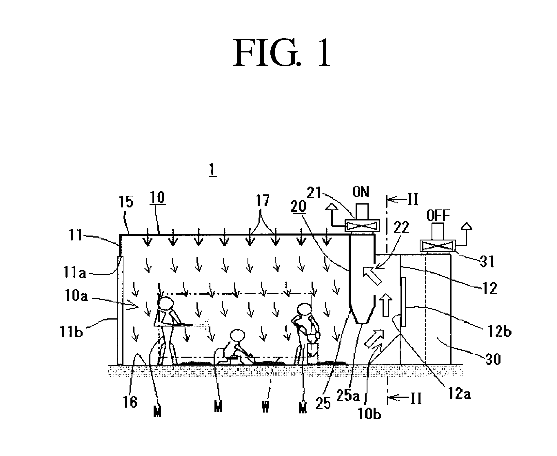
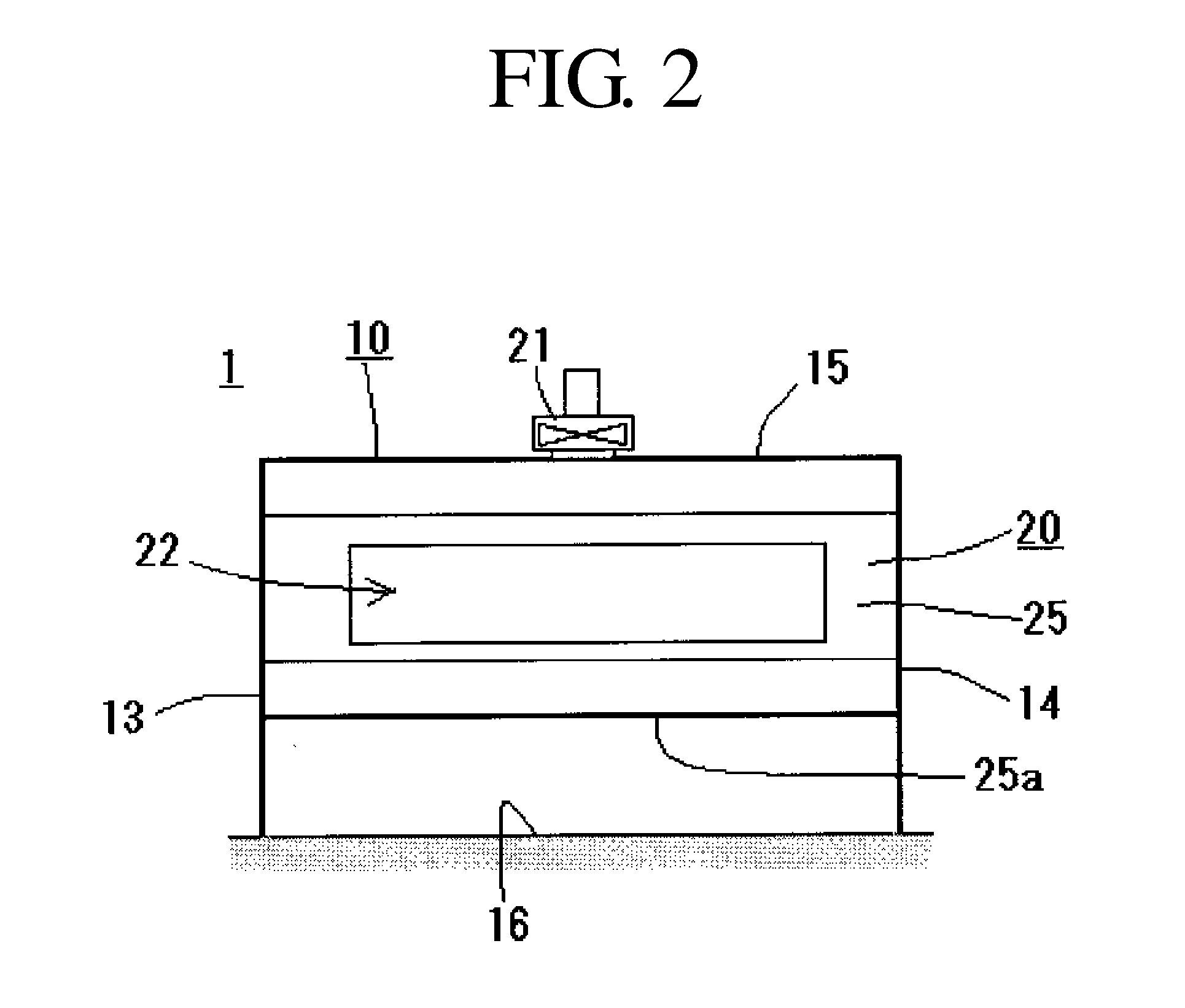
[0076]Reference numeral 1 in FIGS. 1 to 3 is the blasting chamber of the present invention. As shown in FIGS. 1 and 2, although the overall shape thereof is not particularly limited, this working chamber 1 is made so that workers M can enter together with a workpiece W and conduct work, and the working chamber 1 is provided with a substantially box-shaped main unit 10 that is surrounded by side walls 11 to 14, a roof panel 15, and a floor panel 16; a dust collection unit 20 that ventilates the main unit 10 during the blasting process; and a ventilation unit 30 that ventilates the main unit 10 during painting.

Main Unit

[0077]The above-described main unit 10 that constitutes the working chamber 1 of the present invention is a box made of, for example, metal and is formed by two pairs of opposing side walls (11 and 12, and 13 and 14), the roof panel 15, and the floor panel 16. This main unit 10 is formed to have a working space 10a which the worker M can enter toget...

second embodiment

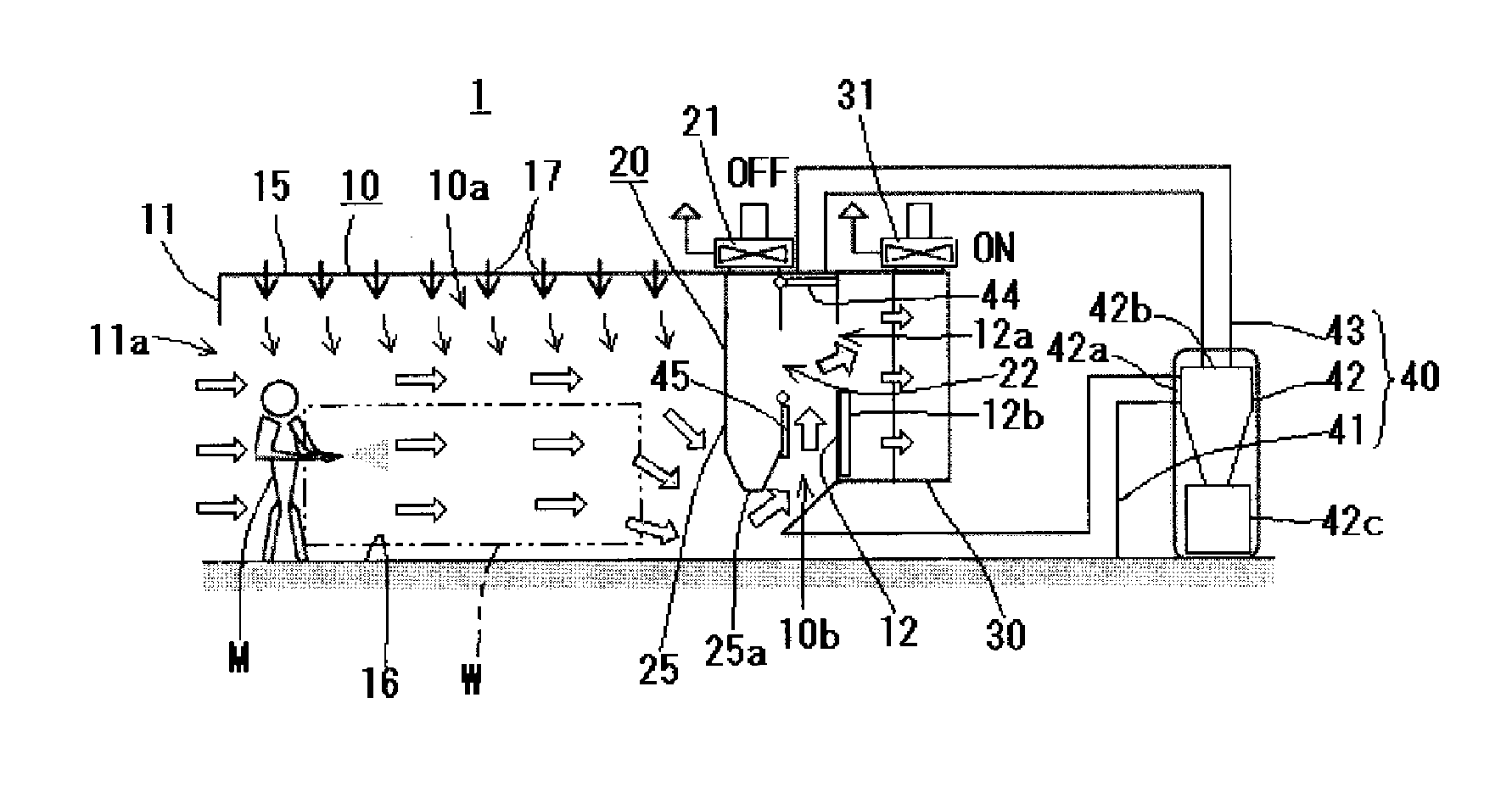
[0126]Another example configuration (Second Embodiment) of the working chamber 1 of the present invention will be described with reference to FIGS. 5 to 7.

[0127]The working chamber 1 of this embodiment, shown in FIGS. 5 to 7, is provided with a collection unit 40 configured of a collecting duct 41, a cyclone 42, and an exhaust duct 43. The working chamber 1 differs from the working chamber 1 of the first embodiment described above with reference to FIGS. 1 to 4 in that second and third opening-and-closing means 44 and 45 are provided in the ventilation duct 10b. The remaining configuration is the same as that of the working chamber 1 of the first embodiment described with reference to FIGS. 1 to 4, and therefore, a description of the common parts will be omitted.

[0128]The cyclone 42 constituting the above-described collection unit 40 generates a swirling flow therein by the airflow passing through the inside, thereby separating and collecting the abrasive to be recycled by collectin...

third embodiment

[0147]As described above, in the second embodiment described with reference to FIGS. 5 to 7, although ventilation of the working space 10a by the dust collection unit 20 through the ventilation duct 10b and collection of the abrasive through the collection unit 40 are conducted alternately, collection of the abrasive from the working space 10a may be conducted simultaneously with ventilation of the working space 10a by the above-described dust collection unit 20.

[0148]An example configuration of the working chamber 1 configured in this way is described with reference to FIGS. 8 and 9, as a third embodiment.

[0149]In the embodiment illustrated in FIGS. 8 and 9, in addition to the collecting duct 41′, the cyclone 42′, and the exhaust duct 43′, the collection unit 40′ is provided with a dust collector 50 equipped with an air-exhaust ventilator 51, and the exhaust duct 43′ communicates with the intake opening of this dust collector 50.

[0150]By laying a perforated plate 61, such as a grat...


PUM


Abstract

A blasting chamber capable of conducting painting on a workpiece subsequent to a blasting process in the same working chamber is provided. A dust collection unit 20 that ventilates a main unit 10 during blasting work and a ventilation unit 30 that ventilates a main unit during a painting step are provided. A side wall 11 of the main unit is provided with an entrance 11a and an opening-and-closing member 11b that opens/closes the entrance, the dust collection unit is provided so as to project from a roof panel 15 to a floor panel 16 at a position closer to an other side wall 12 that is opposed to this side wall so as to partition the interior of the main unit, and a working space 10a and a ventilation duct 10b are defined in the main unit. A roof panel 15 above a working space has air suction holes 17 formed therein, and an intake opening 22 that communicates between the dust collection unit and the ventilation duct is provided. The side wall is provided with an opening 12a that communicates between the ventilation unit and the ventilation duct, and during the blasting process, ventilation is conducted with the dust collection unit with the entrance closed, and during painting, ventilation is conducted with the ventilation unit with the entrance opened.

Description

BACKGROUND OF THE INVENTION[0001]1. Field of the Invention[0002]The present invention relates to blasting chambers or working chambers for a blasting process (in this description, simply referred to as “blasting chambers”), and in particular, to a blasting chamber having formed therein a working space that is large enough so that, when the blasting process is to be conducted on a relatively large-sized workpiece to be processed, one or more workers can enter together with the workpiece and conduct work; and that is adapted to both blasting processing and painting by permitting not only the blasting process, but also painting of the workpiece after the blasting process in the same space.[0003]The term “blasting process” in the present invention is applied in the most broad sense; it includes processes of various types, such as those known as dry ejection or projection (hereinafter referred to as “ejection”, also including projection) in which an abrasive is ejected as a mixed fluid w...

Claims


Application Information

Patent Timeline
Patent Type & Authority Applications(United States)
IPC IPC(8): F24F7/08B24C9/00
CPCB08B15/02Y02P70/179B24C9/006B24C9/00Y02P70/10F24F7/06F24F13/28F24F8/10
Inventor MASE, KEIJIKIKUCHI, RYOJI
Owner FUJI MFG CO LTD
Why Eureka
Try Eureka