Support device for resonator

a support device and resonator technology, applied in auxillary welding devices, mechanical vibration separation, soldering apparatus, etc., can solve the problems of not easy to control abnormal vibration by moving the supporting point of the resonator, vibration loss and/or other abnormal vibration, etc., to achieve faster sound propagation speed, control abnormal vibration, and large logarithmic decrement

Active Publication Date: 2011-02-17
ADWELDS CORP
View PDF6 Cites 31 Cited by
  • Summary
  • Abstract
  • Description
  • Claims
  • Application Information

AI Technical Summary

Benefits of technology

[0014]Based on test results conducted by the present inventor, it has been confirmed that substances that have larger logarithmic decrement and/or faster sound propagation speed are suitable for the substances of the supporting member that support resonators. According to the test results, because substances with large logarithmic decrement are hard to transfer vibration, they absorb abnormal vibration from resonators swiftly, and when the logarithmic decrement of the substances are larger than 0.01 and smaller than 1.0, it is considered that they can control abnormal vibration from resonators effectively (refer to FIGS. 5, 6). Also, because substances that have large sound propagation speed have great speed to transfer vibration, they absorb abnormal vibration from resonators swiftly, and when the sound propagation speed of the substances are larger than 5900 m/s, it is considered that they can control abnormal vibration from resonators effectively (refer to FIGS. 5, 7).
[0015]Accordingly, the supporting means of the support device that is engaged with the portion-to-be-supported and supports the resonator comprises a supporting member which contains substances with 0.01<logarithmic decrement <1.0, the vibration absorbing speed is fast and abnormal vibration which have different directions than that of the resonator is absorbed by the supporting member at the contact point on the resonator, and it becomes possible to let the resonator vibrate at the specified frequency consistently. Accordingly, ultrasonic vibration is applied effectively to the object. Also, because the supporting point of the resonator is not limited to the nodal point and the supporting means is capable of supporting the resonator at any optional point, it is now possible to change the configuration of the device. Moreover, because it is possible to make the size of the supporting means smaller and/or to reduce the number of supporting means, the device can be made smaller and/or simpler.
[0016]Also, the supporting means of the support device that is engaged with the portion-to-be-supported and supports the resonator comprises a supporting member which contains substances with sound propagation speed of more than 5900 m/s, the vibration transferring speed is fast and abnormal vibration which have different directions than that of the resonator is diffused by the supporting member at the co

Problems solved by technology

In the case of the ultrasonic vibration bonding device described in JP No. 2583398B (Paragraphs , , , , , FIG. 2, FIG. 3), as the peripheral surface of the resonator are directly clamped tight mechanically, this condition was the cause of vibration loss and/or other abnormal vibration.
Also, because the resonator is clamped mechanically, friction between the convex portion of the resonator, the supporting members, and the clamping members tends to cause abrasion among them, and it was necessary to clean and/or exchange these members/materials frequently.
Also, there was another problem in which as the friction generates heat, the con

Method used


Image

  • Support device for resonator
  • Support device for resonator
  • Support device for resonator

Examples


first embodiment

The First Embodiment

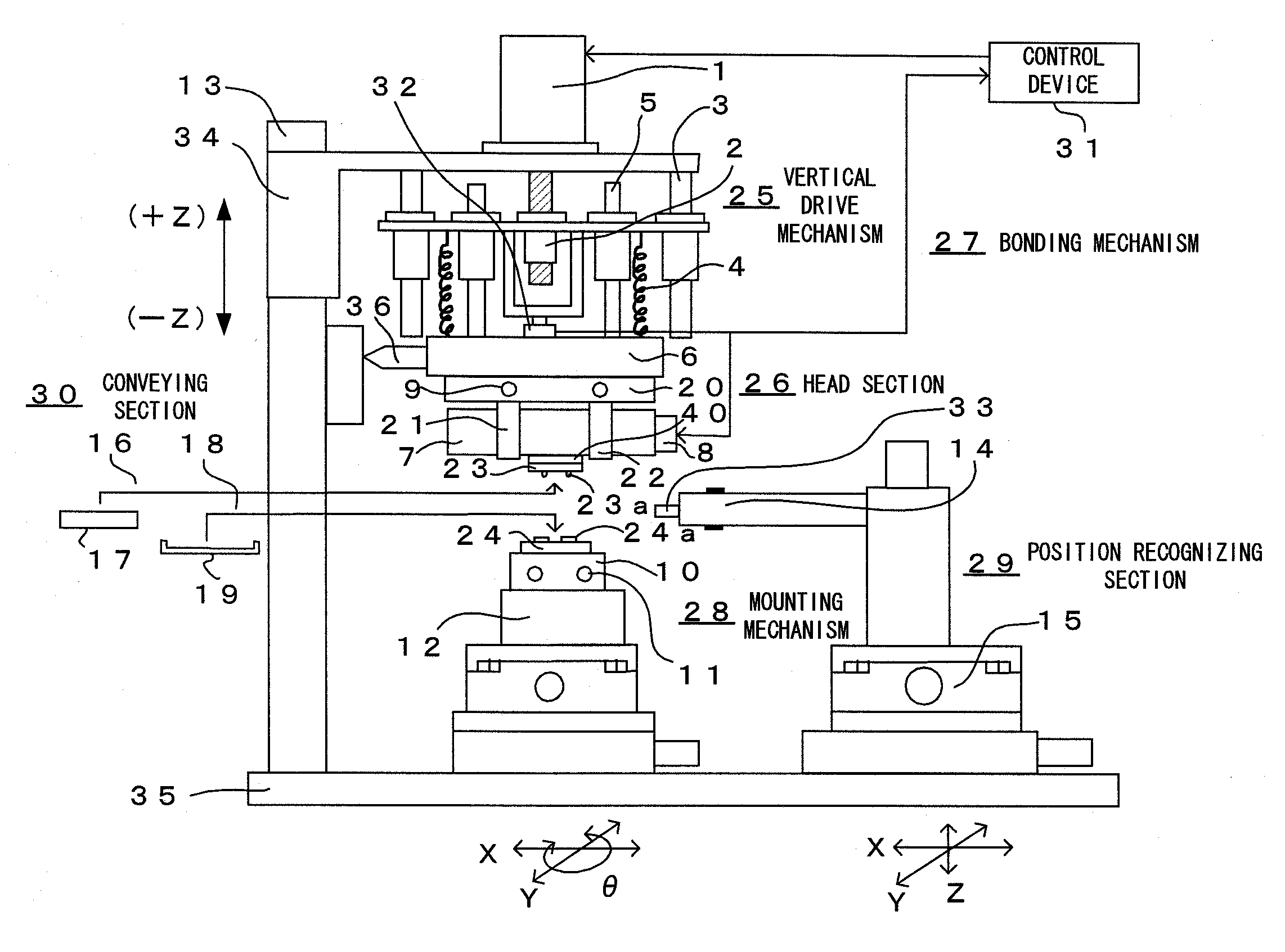
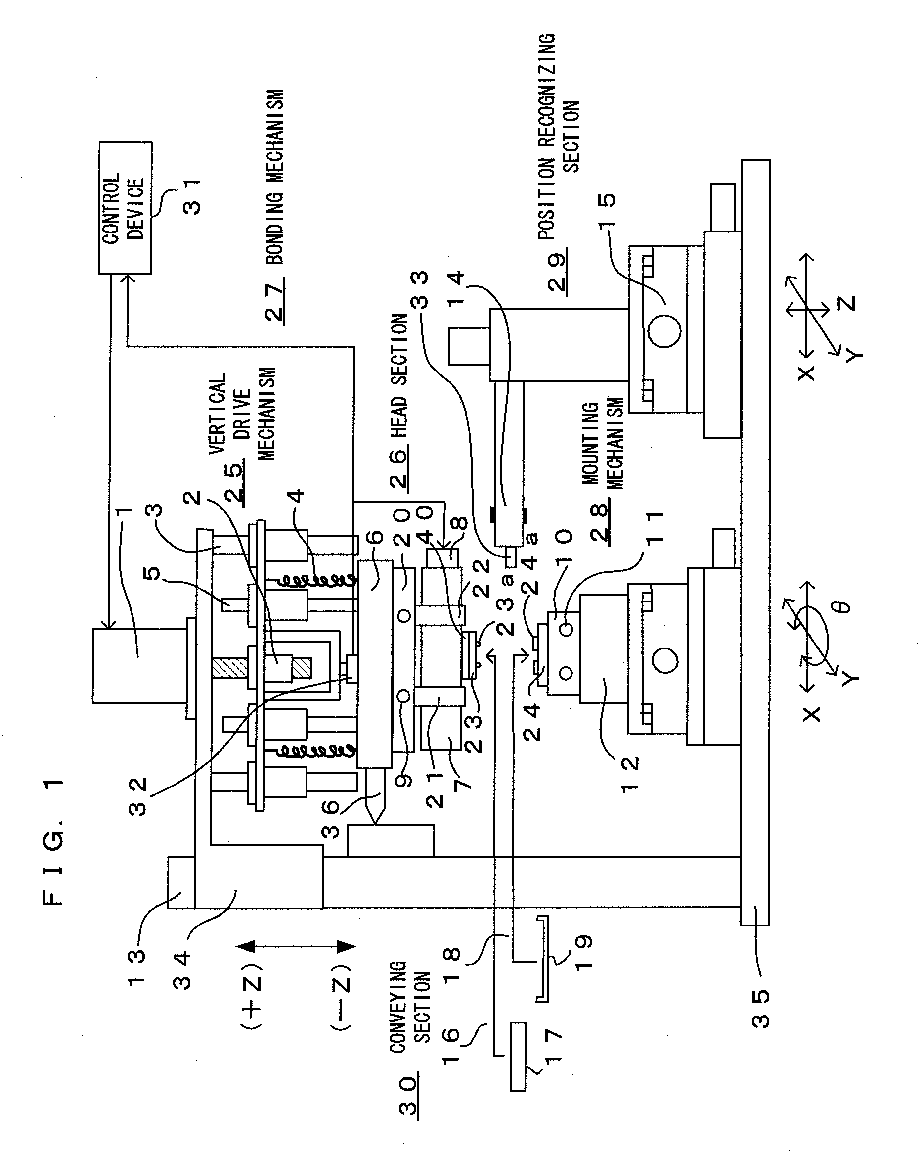
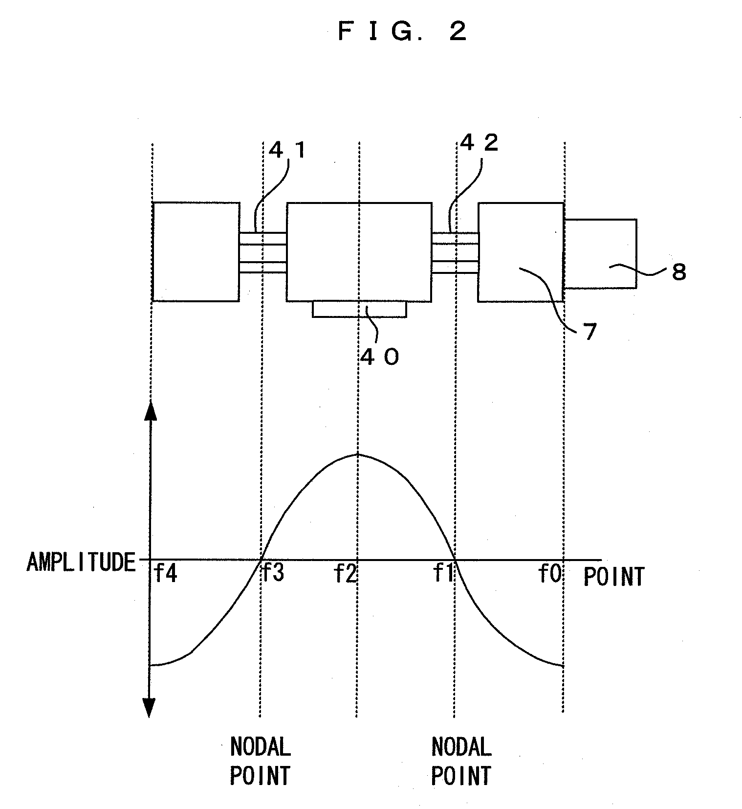
[0036]The first embodiment of the present invention will be described referring to FIG. 1 to FIG. 4. FIG. 1 is a schematic diagram illustrating one embodiment of an ultrasonic vibration bonding device configured with a support device for resonator according to the present invention. FIG. 2 is a diagram illustrating the configuration of the resonator equipped in the ultrasonic vibration bonding device shown in FIG. 1. FIGS. 3A and 3B are a diagram of a resonator supported by a supporting means, FIG. 3A is a front view, FIG. 3B is a right-side view, with an A-A arrow line cross-section of the resonator. FIG. 4 is a basic schematic diagram illustrating an experimental device to measure the vibration amplitude of the supporting means. FIG. 5 is a graph illustrating measured results of vibration amplitudes at specified points of the supporting means, FIG. 6 is a graph illustrating a logarithmic decrement of each substance. FIG. 7 is a graph illustrating sound propagat...

second embodiment

[0100]Next, a second embodiment of the present invention will be described referring to FIGS. 8A to 9B. FIGS. 8A and 8B is a partial schematic diagram illustrating a configuration of an ultrasonic vibration bonding device according to a second embodiment of the present invention, FIG. 8A is a front view, FIG. 8B is a partial cross section. FIGS. 9A and 9B is a partial schematic diagram illustrating a configuration of another example of an ultrasonic vibration bonding device described in FIGS. 8A and 8B, FIG. 9A is a front view, FIG. 9B is a partial cross section. Additionally, the differences from the first embodiment will be described in detail. Note that if the reference characters used in FIGS. 8A to 9B are the same as those used in FIG. 1 to FIG. 4, they are the same or correspondent.

[0101]The point of the ultrasonic vibration bonding device described in the present embodiment that is different from the first embodiment is that resonator 61 with transducer 60 installed is rotate...

third embodiment

[0111]Next, the third embodiment of the present invention will be described referring to FIGS. 10 and 11. FIG. 10 is a partial schematic diagram illustrating a head section and a stage section of an ultrasonic vibration bonding device according to the third embodiment of the presented invention, FIG. 11 is a graph illustrating results of measurements of vibration amplitudes of a resonator and a stage of an ultrasonic vibration bonding device according to the third embodiment of the present invention. Hereinafter, the different points from the first embodiment will be described in detail. Note that if the reference characters used in FIG. 1 to FIG. 9B are the same as those used in FIG. 10, FIG. 11, they are the same or correspondent.

[0112]The points of the ultrasonic vibration bonding device of the present embodiment from the first embodiment that are different from the first embodiment are, in addition to the fact that first clamping means 21 and second clamping means 22 are compose...


PUM

PropertyMeasurementUnit
Speedaaaaaaaaaa

Abstract

The purpose of this invention is to provide a support device for a resonator that can support the resonator at an optional location, can let the resonator vibrate with a specified vibration consistently, and can apply an ultrasonic vibration to objects efficiently. By inserting first clamping means and second clamping means, which comprise supporting member at least at each contacting portion, into first portion-to-be-supported and second portion-to-be-supported of resonator, the resonator is supported. As substances of the supporting member, substances that have a logarithmic decrement higher than 0.01 and lower than 1.0 and/or a sound propagation speed of more than 5900 m/s are suitable.

Description

BACKGROUND OF THE INVENTION[0001]The present invention relates to a support device for resonator, which supports a resonator resonating by ultrasonic vibration of a transducer.[0002]Conventionally, there are technologies to process objects by utilizing ultrasonic vibration, such as an ultrasonic vibration bonding device that bonds multiple objects by providing ultrasonic vibration to these objects which are placed on top of each other, using an ultrasonic cutting device that cuts objects by providing ultrasonic vibration on cutting devices, using an ultrasonic grinding device to grind objects by providing ultrasonic vibration on grinding devices, etc.[0003]These apparatus, which utilize ultrasonic vibration, generally have resonators with transducers, and these transducers provide vibrations that are adjusted to the natural vibration frequencies of each resonator, then the vibration are amplified by the resonators, and the ultrasonic vibrations are applied to objects effectively.[00...

Claims


Application Information

Patent Timeline
IPC IPC(8): H01L21/60
CPCH01L21/67092H01L2924/014H01L24/75H01L24/81H01L2224/29116H01L2224/75H01L2224/75355H01L2224/75801H01L2224/81121H01L2224/81205H01L2224/81801H01L2924/01004H01L2924/01013H01L2924/01025H01L2924/01029H01L2924/01033H01L2924/01047H01L2924/01079H01L2924/01082H01L2924/30105H01L2924/01005H01L2924/01006H01L2924/01019H01L2924/0105H01L2924/01074H01L21/67144H01L2924/12042B06B3/00B23K20/106H01L2924/00
Inventor NAKAI, SEIYA
Owner ADWELDS CORP
Why Eureka
Try Eureka