Lamp structure

a technology of light source and structure, applied in the direction of discharge tube main electrodes, semiconductor devices of light sources, lighting and heating apparatus, etc., can solve the problems of reducing the overall light emission increasing the temperature of the led, and reducing the efficiency of the led, so as to improve the heat dissipation convection

Inactive Publication Date: 2011-02-17
RISUN EXPANSE
View PDF4 Cites 128 Cited by
  • Summary
  • Abstract
  • Description
  • Claims
  • Application Information

AI Technical Summary

Benefits of technology

[0014]Therefore, in view of the above problems, the present invention provides a lamp structure, so as to improve a heat dissipation convection effect inside the lamp and eliminate the problem of noise impulse of the lamp in the prior art.
[0016]The effect of the present invention is as follows. The light-emitting element (LED) is attached to the heat sink of the lamp housing, so as to take advantage of the characteristics of the LED such as no idling time, quick response, a small size, low power consumption, low pollution, high brightness, and long lifespan. The airflow is taken in through the air intake holes on two opposite sides of the lamp housing by using the fan, and guided to be blown to the heat dissipation fins for heat dissipation, and ventilated through the vent holes after dissipation. Thus, double circulatory heat exchange convection is realized, thus effectively improving the heat dissipation efficiency and extending the overall use life of the LED.
[0017]The aforementioned fan may be a blower fan. Through a structure design in which the blower fan is surrounded by a plurality of heat dissipation fins, the side airflow generated by the blower fan may smoothly and evenly pass through the airflow passages between the plurality of heat dissipation fins without air resistance, so that the noise of the blower fan is decreased due to the uniform flow field without turbulence.

Problems solved by technology

As the heat amount generated by the unit area of the LED is large, after long time of use, the generated heat energy is accumulated and cannot be dissipated, which causes that the temperature of the LED rises with time, and also the ambient temperature rises, so that the overall light emission efficiency of the LED is reduced.
Therefore, the temperature is a major factor that determines the light emission efficiency and lifespan of the LED and is also the major barrier for the application of the LED in the illumination lamps.
Additionally, currently most illumination lamps are made of light weight material, so the trend of the thin design results in smaller space inside the illumination lamp, which causes that the heat energy emitted by the LED is easily accumulated inside the small space inside the illumination lamp and the heat energy cannot be guided to the outside environment, thus greatly reducing the efficiency of the LED and shortening the lifespan of elements of the LED, and relatively shortening an overall use life of the illumination lamp.
If the LED module is sealed inside the illumination lamp structure as a whole, as no heat dissipation measures are adopted, the accumulated heat energy of the LED cannot be quickly dissipated, so the use efficiency and life of the LED are easily affected, and even an overheat damage occurs to internal chips, thus further increasing a damage rate of the illumination lamp.
However, more heat dissipation fins may easily result in even smaller airflow passages between the heat dissipation fins and further increase air resistance that the airflow is blown to the airflow passages (that is, turbulence occurs), such that the airflow is blocked and the original smooth airflow passages are affected.
If the rotation speed of the axial fan is further increased to increase the flow quantity, a noise impulse (dynamic noise) occurs under the influence of the air resistance, and together with the noise generated by the electronic devices of the lamp during operation, the overall noise level and prominence ratio of the lamp are increased.

Method used


Image

  • Lamp structure
  • Lamp structure
  • Lamp structure

Examples


Embodiment Construction

[0028]In order to make the objectives, structures, characteristics, and functions of the present invention more comprehensive, the embodiments are illustrated in detail as follows.

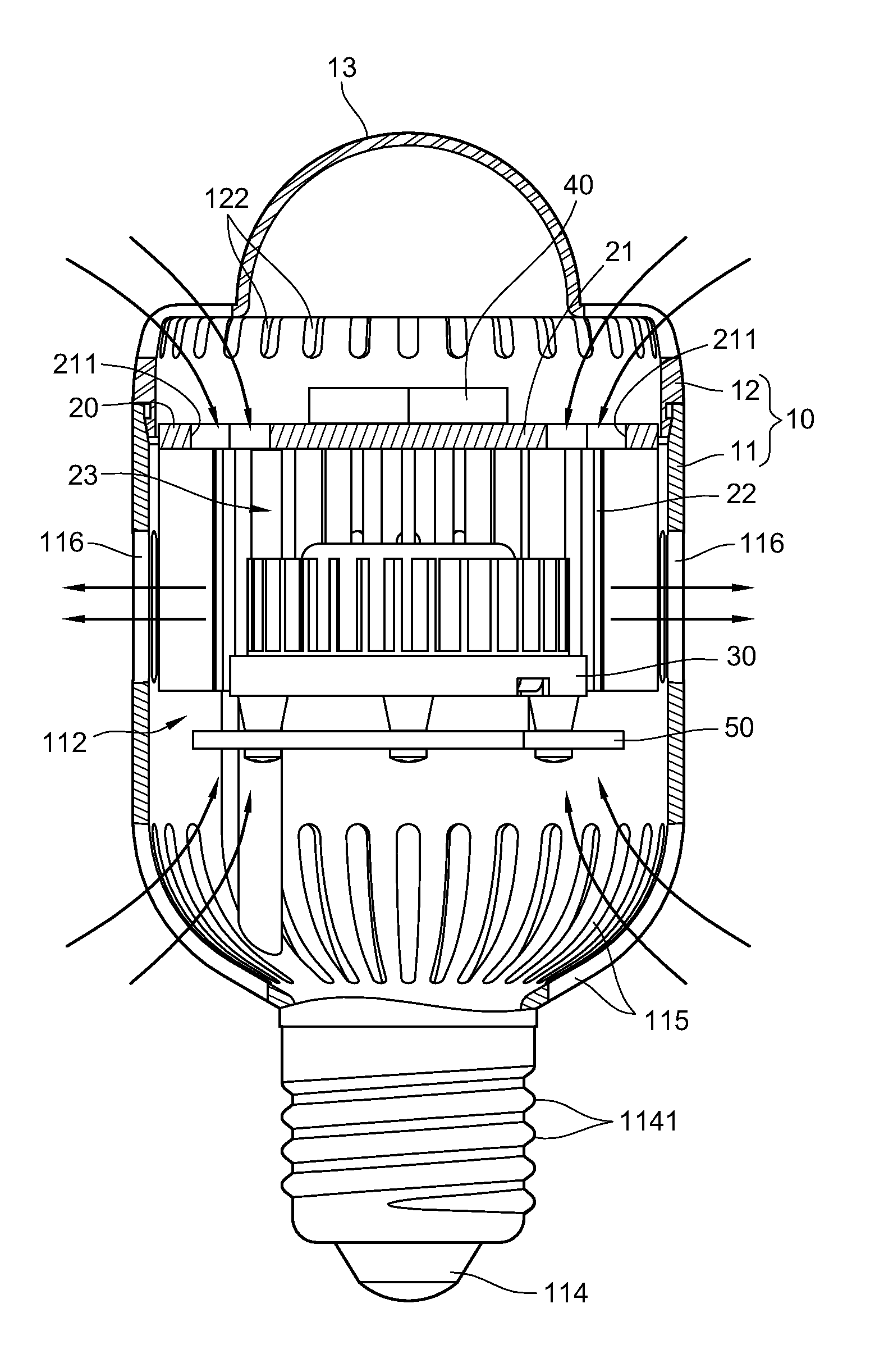
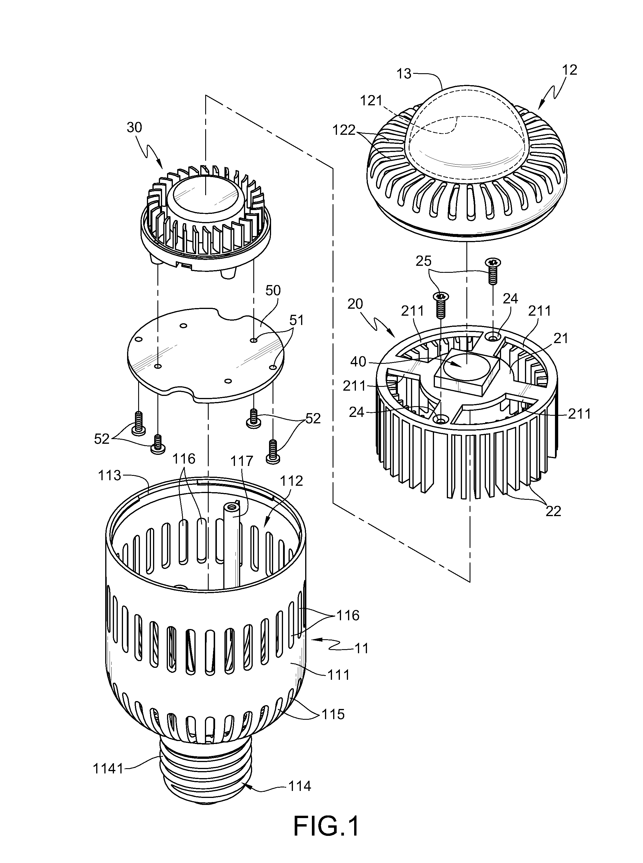
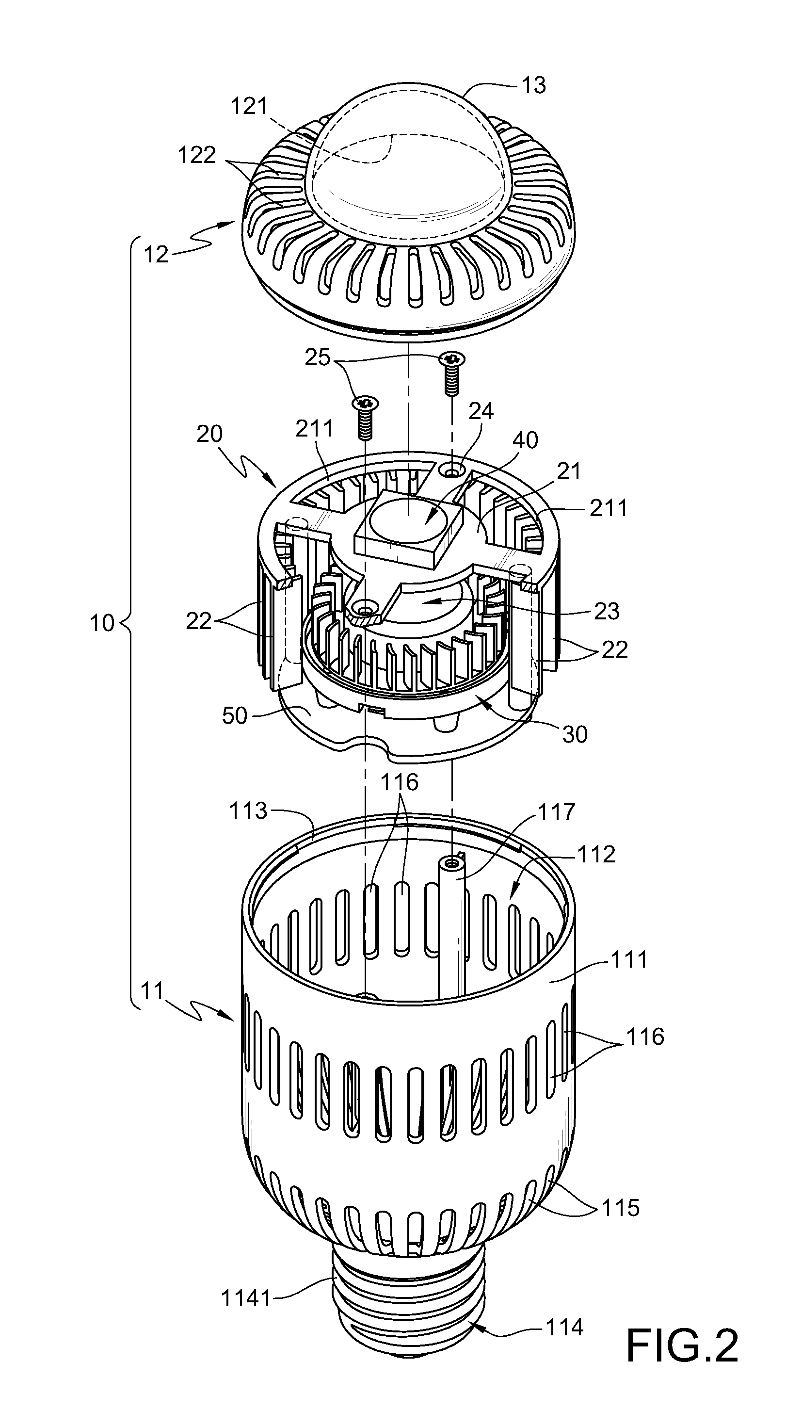
[0029]As shown in FIGS. 1, 2, and 3, FIG. 1 is a schematic exploded view according to a first embodiment of the present invention. FIG. 2 is a schematic partial combination view according to the first embodiment of the present invention. FIG. 3 is a schematic sectional view according to the first embodiment of the present invention.

[0030]The lamp structure of the present invention substantially comprises a lamp housing 10, a heat sink 20, and a fan 30. The lamp housing 10 has a body 11 and a cover 12. The body 11 has a surrounding wall 111 that surrounds along a vertical axis, and a chamber 112 is defined inside the surrounding wall 111. An opening 113 is formed on one side of the body 11, and an electrically conductive portion 114 is disposed on the other side of the body 11.

[0031]The electrically conduct...


PUM


Abstract

A lamp structure includes a lamp housing. A plurality of air intake holes is respectively opened on two opposite sides of the lamp housing, and a plurality of vent holes is opened between the plurality of air intake holes on the two sides. A heat sink and a light-emitting element disposed on the heat sink are disposed inside the lamp housing. The heat sink is surrounded by a plurality of heat dissipation fins to form an accommodation chamber for accommodating a fan. When activated, the fan intakes an airflow respectively through the plurality of air intake holes on two sides of the lamp housing, blows the airflow to the plurality of heat dissipation fins, and ventilates the hot air through the vent holes, thereby realizing a double circulatory heat convection exchange effect.

Description

CROSS-REFERENCE TO RELATED APPLICATIONS[0001]This non-provisional application claims priority under 35 U.S.C. § 119(a) on Patent Application No(s). 098215056 filed in Taiwan, R.O.C. on Aug. 14, 2009, the entire contents of which are hereby incorporated by reference.BACKGROUND OF THE INVENTION[0002]1. Field of Invention[0003]The present invention relates to a lamp structure, and more particularly to a lamp structure having double circulatory convection heat dissipation.[0004]2. Related Art[0005]A light emitting diode (LED) has advantages such as power saving, small weight, long lifespan, a low driving voltage, a fast response speed, good vibration resistance. Along with the progress of the fabrication techniques of the LED, the LED also develops towards high brightness, multicolor, and high light emission efficiency. As unit brightness of the LED increases ceaselessly, together with a feature of the LED that more than 80% power is saved, the application field of the LED becomes wider...

Claims


Application Information

Patent Timeline
Patent Type & Authority Applications(United States)
IPC IPC(8): H01J61/52
CPCF21V29/02F21Y2101/02F21K9/135F21V29/83F21V29/673F21V29/74F21V29/773F21V29/507F21K9/232F21Y2115/10
Inventor HUANG, CHIANG CHENG
Owner RISUN EXPANSE
Why Eureka
Try Eureka