Clock and data recovery circuit of a source driver and a display device

Active Publication Date: 2011-02-17
SAMSUNG ELECTRONICS CO LTD
View PDF7 Cites 83 Cited by
  • Summary
  • Abstract
  • Description
  • Claims
  • Application Information

AI Technical Summary

Benefits of technology

[0007]Some example embodiments provide a clock and data recovery circuit of a

Problems solved by technology

Since data and a clock signal are separately transmitted through a data line and a clock signal line, respectively, these conventional interfaces have an inevitable skew issue.
In particular, in a dis

Method used


Image

  • Clock and data recovery circuit of a source driver and a display device
  • Clock and data recovery circuit of a source driver and a display device
  • Clock and data recovery circuit of a source driver and a display device

Examples


Example

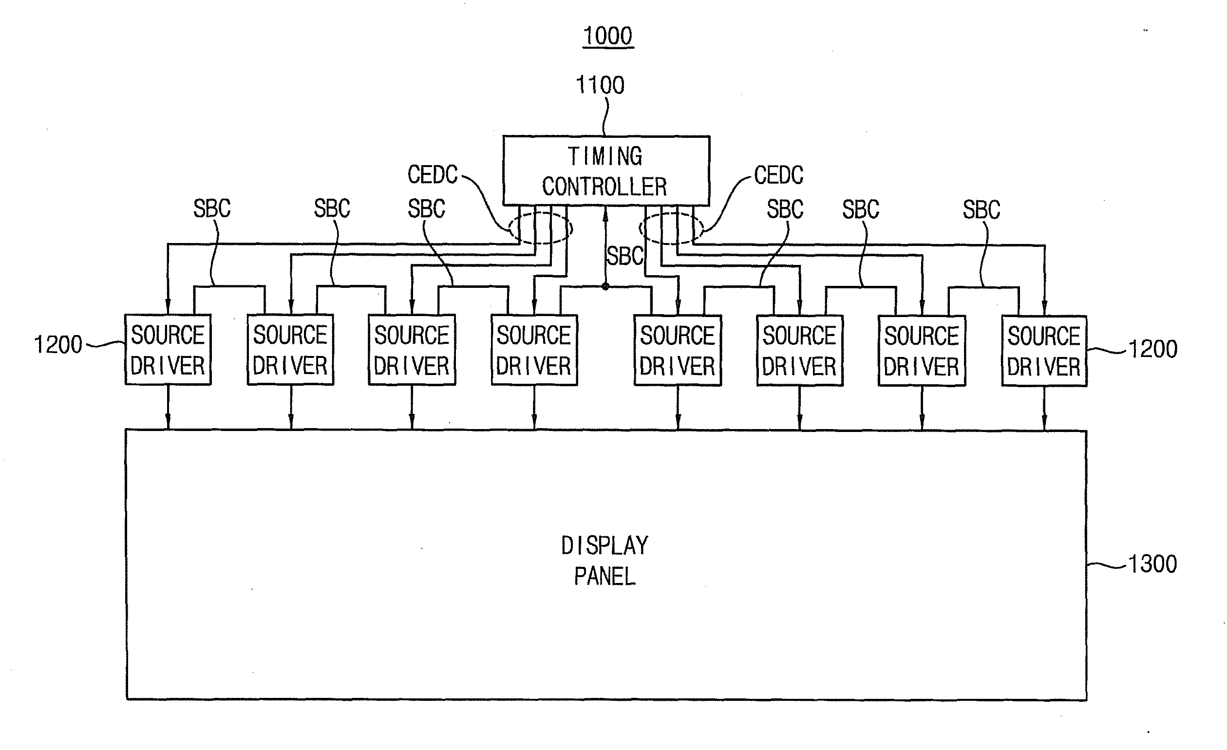
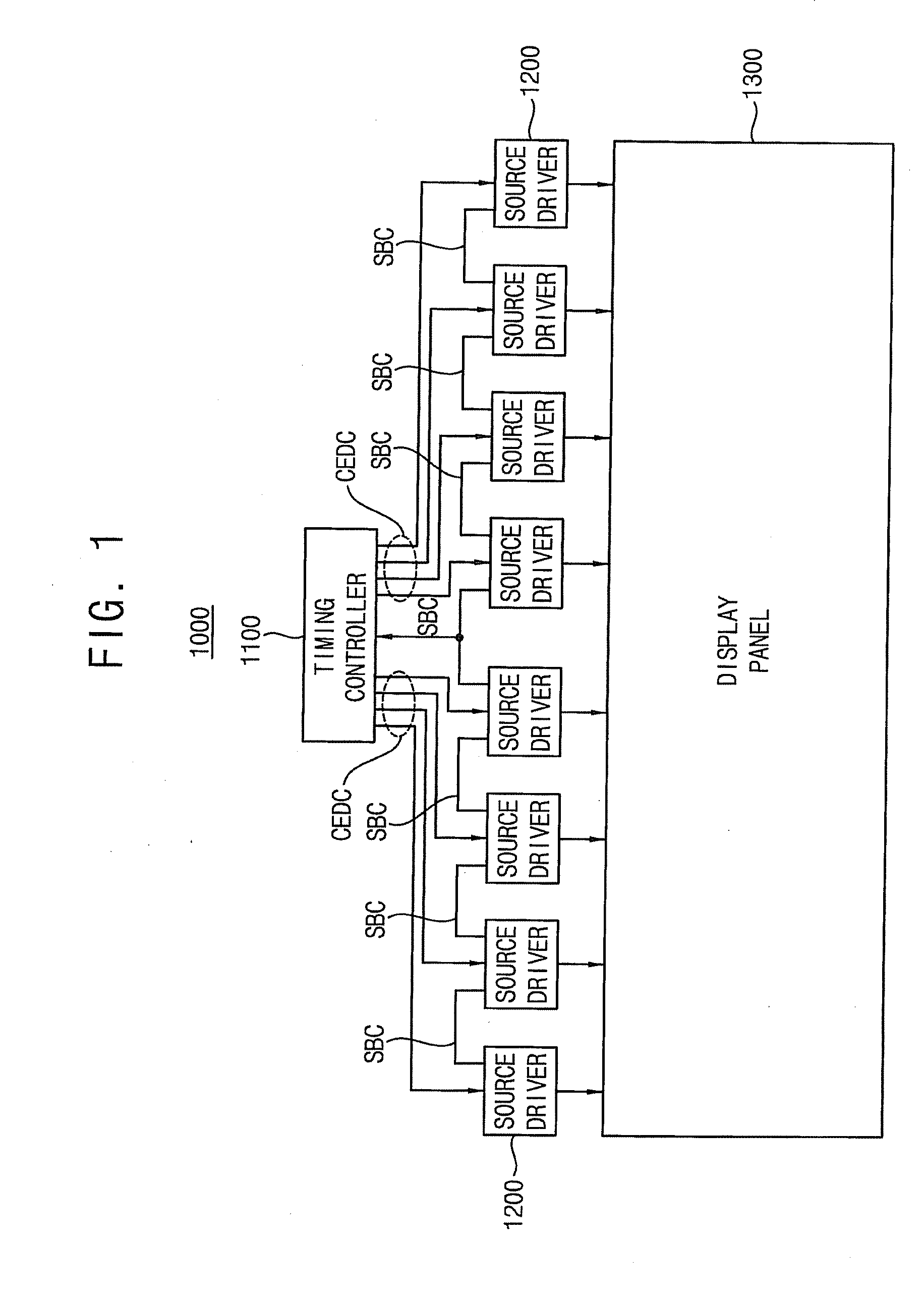
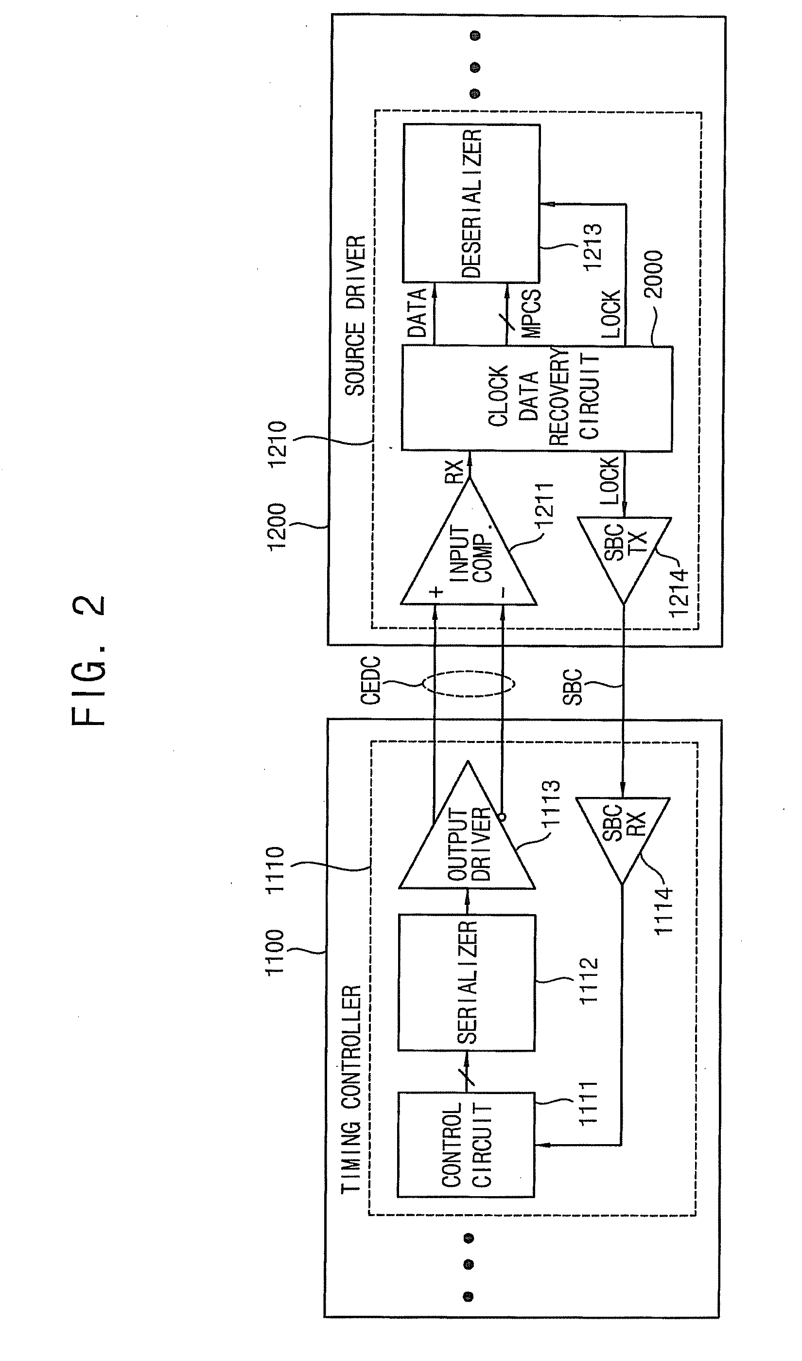
[0062]Various example embodiments will be described more fully hereinafter with reference to the accompanying drawings, in which some example embodiments are shown. The present inventive concepts may, however, be embodied in many different forms and should not be construed as limited to the example embodiments set forth herein. Rather, these example embodiments are provided so that this disclosure will be thorough and complete, and will fully convey the scope of the present inventive concept to those skilled in the art. In the drawings, the sizes and relative sizes of layers and regions may be exaggerated for clarity. Like numerals refer to like elements throughout.

[0063]It will be understood that, although the terms first, second, third etc. may be used herein to describe various elements, these elements should not be limited by these terms. These terms are used to distinguish one element from another. Thus, a first element, component, region, layer or section discussed below could...


PUM


Abstract

A clock and data recovery (CDR) circuit of a source driver includes a clock recovery unit and a delay locked loop unit. The clock recovery unit receives data bits and a clock code periodically inserted into the data bits through a clock embedded data channel in a display data mode, and is configured to generate a clock signal by detecting an edge of the clock code. The delay locked loop unit is configured to generate a multi-phase clock signal based on the clock signal in the display data mode.

Description

CROSS-REFERENCE TO RELATED APPLICATION(S)[0001]This application claims priority under 35 USC §119 to Korean Patent Application No. 2009-0074856, filed on Aug. 13, 2009, in the Korean Intellectual Property Office (KIPO), the contents of which are incorporated herein in its entirety by reference, and to Korean Patent Application No. 2009-0079157, filed on Aug. 26, 2009, in the Korean Intellectual Property Office (KIPO), the contents of which are incorporated herein in its entirety by reference.BACKGROUND[0002]1. Technical Field[0003]Example embodiments relate to an intra-panel interface, and more particularly to a clock and data recovery circuit of a source driver and a display device.[0004]2. Description of the Related Art[0005]A display device employs an intra-panel interface for transferring data from a timing controller to source drivers. For example, reduced swing differential signaling (RSDS), mini low voltage differential signaling (mini-LVDS), point-to-point differential signa...

Claims


Application Information

Patent Timeline
IPC IPC(8): G06F3/038
CPCG09G5/008G09G2310/0275H03L7/0805H03L7/0816H04L25/0272H04L7/044H04L7/046H04L7/08H04L7/0004
Inventor LIM, JUNG-PILLEE, JAE-YOULPAE, HAN-SUBAEK, DONG-HOON
Owner SAMSUNG ELECTRONICS CO LTD
Why Eureka
Try Eureka