Led lamp and cooling method thereof

a technology of led lamps and cooling methods, which is applied in the direction of fixed installations, lighting and heating apparatus, lighting support devices, etc., can solve the problems of reducing changing wavelengths, and generating a large amount of heat, so as to reduce the brightness of led lamps, reduce the use life, and reduce the effect of heat dissipation

Inactive Publication Date: 2011-02-17
LEOTEK ELECTRONICS
View PDF12 Cites 25 Cited by
  • Summary
  • Abstract
  • Description
  • Claims
  • Application Information

AI Technical Summary

Benefits of technology

[0009]One particular aspect of the present invention is to provide an LED lamp and a cooling method thereof. The LED lamp can dissipate heat smoothly, distribute the flow field uniformly, be easily manufactured, reduces cost and weight, and be expanded.

Problems solved by technology

When LED is lighting, a great amount of heat is generated so that a cooling device is required to dissipate the heat.
When the cooling device is not designed well, high temperature will lower the brightness of LED, reduce the usage life, and change the wavelength.
1. The LED lighting device 1a of the prior art usually has a housing 11a and an LED light source device 12a. The LED light source device 12a is directly pasted onto the housing 11a. The light source emits from the bottom of the housing 11a. The housing 11a has a cooling fin 111a with a large dimension to directly exhaust heat to air. However, dust will be accumulated on the housing 11a to affect the cooling effect. Moreover, the thickness of the housing 11a needs to be increased to make the heat be distributed uniformly and the housing 11a is made of heat-conductive metal. The cost and the weight increases.
2. A cooling pipe (not shown in the figure) is used to dissipate the heat of the LED. That will increase the cost and it is difficult to maintain the LED lighting device. Furthermore, due to the system dimension is increased and the LED lighting device becomes complex, it is not to assemble the LED lighting device.
3. Reference is made to FIG. 2. The LED lighting device 2a of the prior art includes a housing 21a and an LED light source device 22a. The bottom of the housing 21a is flat. The bottom of the housing 21a has an air inlet 211a. The LED light source device 22a is located in the housing 21a. When air is blown into the lamp via the air inlet 22a (the airflow path is shown in the figure), part of the LED light source device 22a cannot be blown by air to form a death zone of airflow. The cooling effect is affected.

Method used


Image

  • Led lamp and cooling method thereof
  • Led lamp and cooling method thereof
  • Led lamp and cooling method thereof

Examples


Embodiment Construction

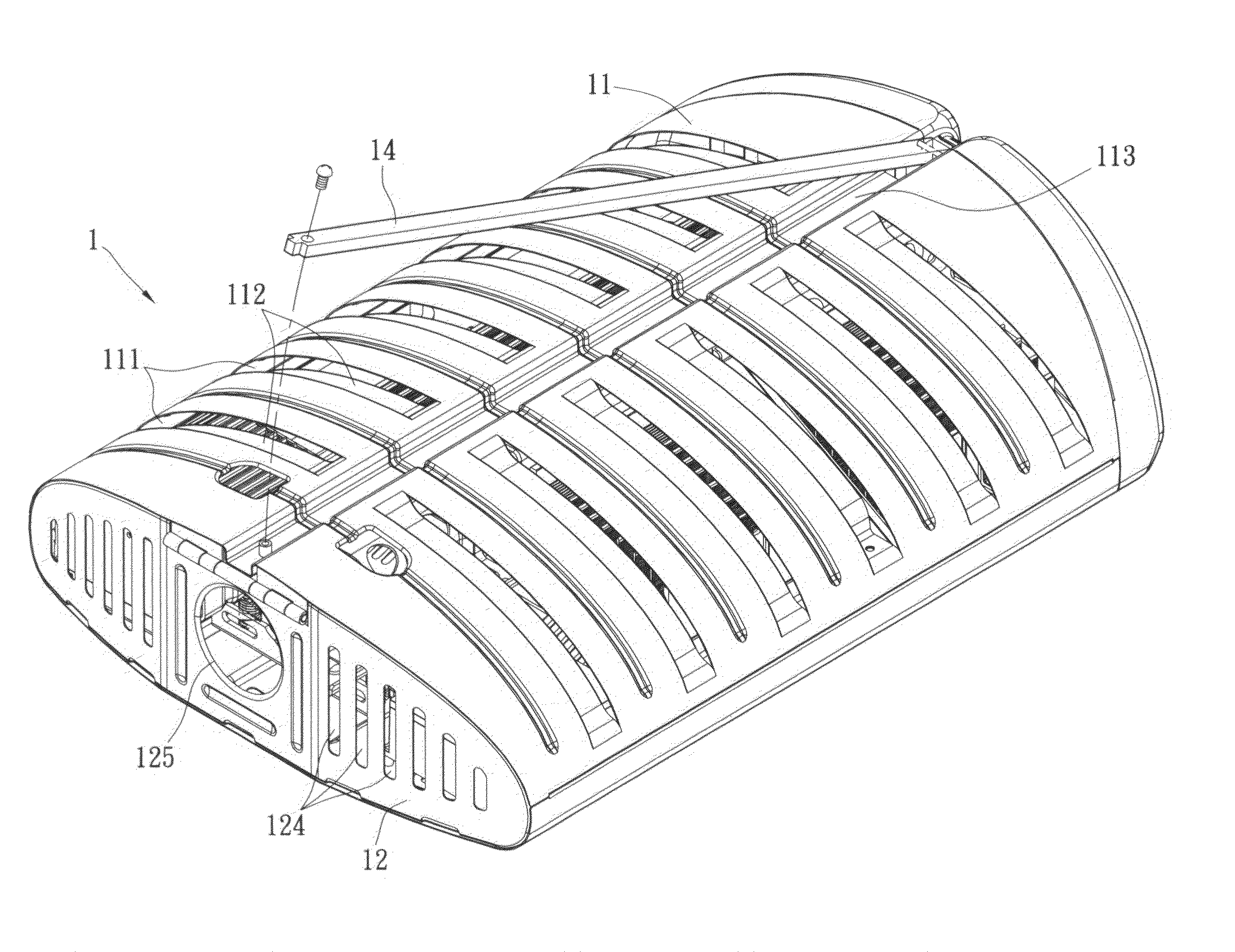
[0031]Reference is made to FIGS. 4˜8. The LED lamp includes a housing 1, at least one LED light source module 2 and a power supply 3.

[0032]The housing 1 is hollow and is made of metal or plastic. The housing 1 includes a cover and 11 and a base 12. In this embodiment, the cover body is pivoted with the base, but not limited to above. The cover body 11 and the base 12 form a cooling space 13.

[0033]The cover body 11 has a plurality of air outlets 111, a plurality of concave portions 112 and a trough 113. The air outlets 111 of the cover body 11 are rectangular and are disposed at the top of the cover body 11 at interval and located at two sides of the trough 113. The concave portions 112 are respectively located at the air outlets 111 and its height is lower than the height of the cover body 11 to prevent dust or rain from entering into the housing 1. The trough 113 can receive a support rod 14. One end of the support rod 14 is pivoted with one end of the cover body 11, and another en...


PUM


Abstract

A cooling method for an LED lamp is disclosed. An LED lamp is provided. The LED lamp includes a housing and at least one LED light source module. The housing has a cover body, a base and a plurality of air outlets. The base forms at least one segment difference portion. The slanted surface of the segment difference portion has a plurality of air inlets. The LED light source module is adjacent to the air inlets. The LED light source module has a cooling device and the cover body has a plurality of air outlets. Airflow is guided into the cooling space along the air inlet on the slanted surface of the segment difference portion. When the LED lamp generates heat, air entered into the cooling space is blown to the cooling device. The airflow with heat is exhausted from the air outlet of the cover body.

Description

BACKGROUND OF THE INVENTION[0001]1. Field of the Invention[0002]The present invention relates to an LED lamp and a cooling method thereof. In particular, the present invention relates to an LED lamp that dissipates heat smoothly, distributes the flow field uniformly, and reduce cost and weight and a cooling method thereof.[0003]2. Description of Related Art[0004]Because LED has a lot of merits, such as brightness is high, consumption power is low, and usage life is long, etc, LED is popularly applied to a variety of lighting devices, such as an LED streetlamp for lighting a road. When LED is lighting, a great amount of heat is generated so that a cooling device is required to dissipate the heat. Therefore, LED can light under a proper temperature and does not burn down. When the cooling device is not designed well, high temperature will lower the brightness of LED, reduce the usage life, and change the wavelength.[0005]Reference is made to FIG. 1, the LED lighting device of the prio...

Claims


Application Information

Patent Timeline
Patent Type & Authority Applications(United States)
IPC IPC(8): F21S4/00
CPCF21S8/086F21V29/004F21W2131/103F21V29/83F21V29/71F21V29/76F21Y2101/02F21Y2115/10
Inventor HU, SHENG-HSIUNG
Owner LEOTEK ELECTRONICS
Why Eureka
Try Eureka