Ribbon microphone unit and ribbon microphone

a microphone and ribbon technology, applied in the direction of electrical transducers, transducer types, electric transducers, etc., can solve the problems of deformation of the frequency characteristics, and malfunction of the microphone, so as to prevent the deformation and prevent the degradation of the frequency characteristics of the microphone incorporating the ribbon diaphragm due to impact force

Inactive Publication Date: 2011-02-17
AUDIO-TECHNICA
View PDF5 Cites 9 Cited by
  • Summary
  • Abstract
  • Description
  • Claims
  • Application Information

AI Technical Summary

Benefits of technology

[0019]The elastic layer is provided at least at the portion of the ribbon diaphragm, the portion vibrating upon receiving sound waves. Thus, the force applied to the ribbon diaphragm leading to the deformation of the ribbon microphone is countered by

Problems solved by technology

This leads to the degradation of frequency characteristic and malfunctioning of the microphone.
This extremely degrades the frequency characteristics and may cause malfunctioning of the whole system.
However, no countermeasure has been taken for an impact force applied at a situation other than transportation such as a case where the ribbon micr

Method used


Image

  • Ribbon microphone unit and ribbon microphone
  • Ribbon microphone unit and ribbon microphone
  • Ribbon microphone unit and ribbon microphone

Examples


Embodiment Construction

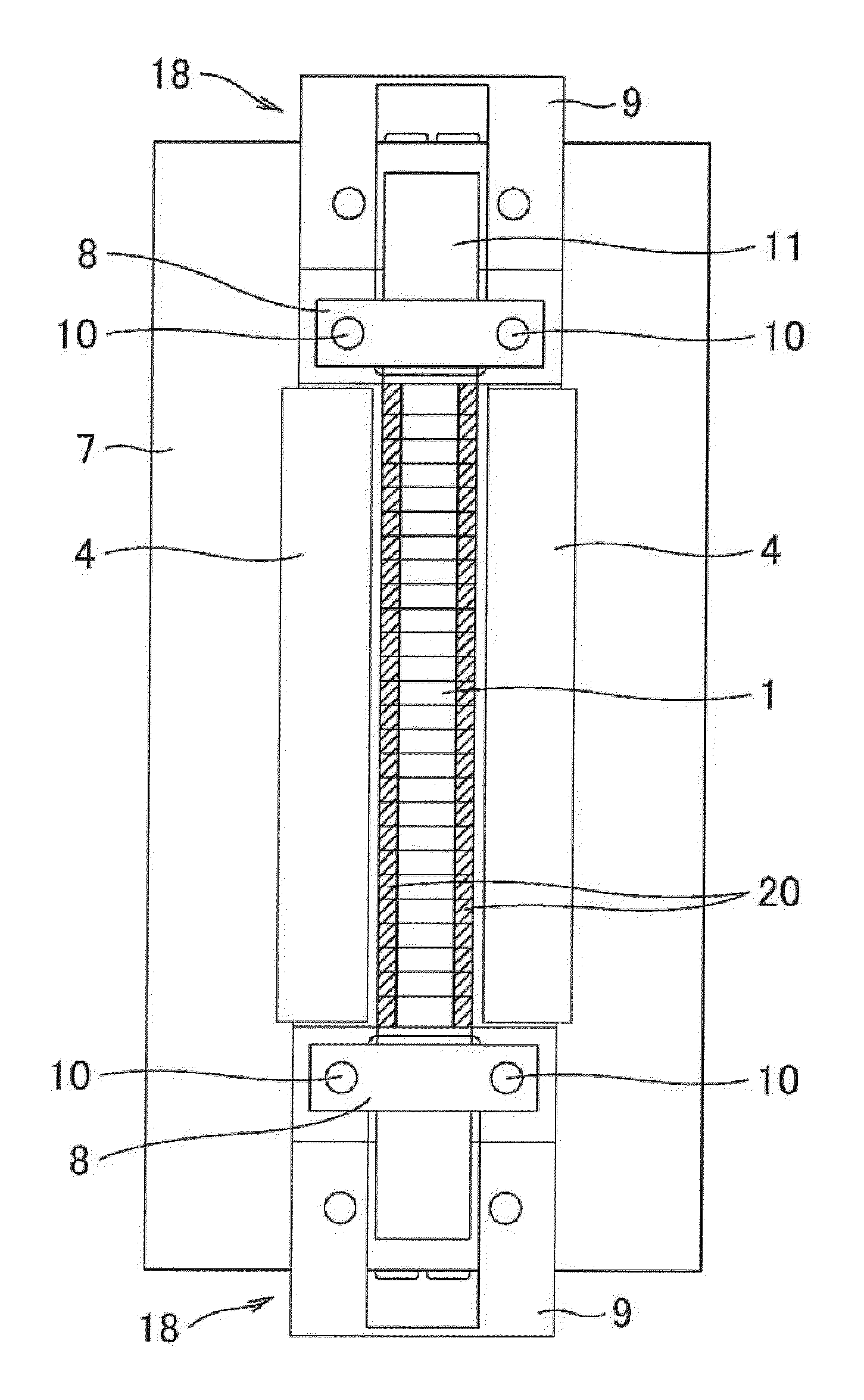
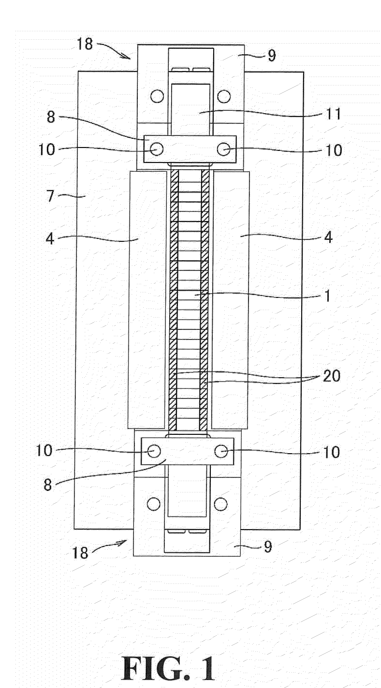
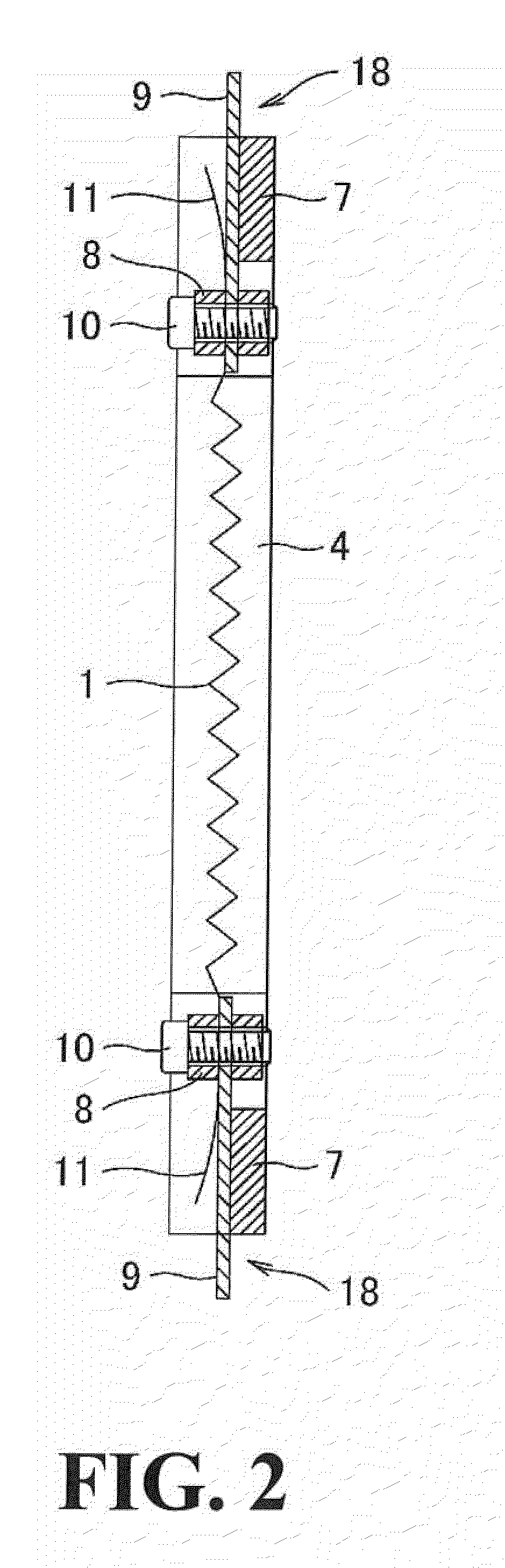
[0030]An embodiment of a ribbon microphone unit and a ribbon microphone according to the present invention is described with reference to FIGS. 1 to 4. The feature of the present invention lies in a structure of the ribbon diaphragm (hereinafter, simply referred to as ribbon). Since the embodiment of the present invention has major part of the structure identical to that of the conventional example, the identical elements are given the same reference numerals.

[0031]In FIGS. 1 and 2, the ribbon microphone unit has a frame 7 having a shape of a rectangular frame that is long in the vertical direction. A pair of permanent magnets 4 is fixed to inside surfaces of the frame 7. The permanent magnets 4 are disposed at respective sides of the frame 7 along the length direction with a certain space therebetween. The permanent magnets 4 are polarized in the width direction (right / left direction in FIG. 1). The polarizing directions of the pair of permanent magnets 4 are the same and a paralle...


PUM


Abstract

A ribbon microphone unit includes a permanent magnet that forms a magnetic field and a ribbon diaphragm that is disposed in the magnetic field and vibrates upon receiving a sound wave. An elastic layer made of synthetic resin is formed at least at a portion of the ribbon diaphragm, the portion vibrating upon receiving the sound wave. Preferably, the ribbon diaphragm is formed into triangular waves with the portion vibrating upon receiving sound waves being alternately folded along lines in a width direction across the entire length. The elastic layer may be formed on one or both surfaces of the ribbon diaphragm and may be provided only at both side ends of the ribbon diaphragm.

Description

BACKGROUND OF THE INVENTION[0001]1. Field of the Invention[0002]The present invention relates to a ribbon microphone unit and a ribbon microphone in which damage on a ribbon diaphragm due to impact applied to the ribbon microphone unit and the ribbon microphone during transportation and upon installation is either prevented or reduced.[0003]2. Description of the Related Art[0004]A ribbon microphone mainly includes a pair of magnets for forming a magnetic field and a ribbon diaphragm. The magnets in pair are arranged in parallel at both sides of the ribbon diaphragm while being apart from the ribbon diaphragm for a certain space. The magnets form a magnetic field therebetween in which the ribbon diaphragm is arranged. The ribbon diaphragm is generally formed of an aluminum foil having a thickness of several micrometers. Aluminum is suitable as a material of a ribbon diaphragm of the ribbon microphone because its conductivity is better and its specific gravity is lower as compared wit...

Claims


Application Information

Patent Timeline
IPC IPC(8): H04R23/00H04R1/02
CPCH04R9/08H04R9/048
Inventor AKINO, HIROSHI
Owner AUDIO-TECHNICA
Why Eureka
Try Eureka