Continuous porous flow distributors for a fuel cell

a distributor and porous flow technology, applied in the field of fuel cell systems, can solve the problems of reactant flow maldistribution, poor fuel cell performance, increased manufacturing costs and the use of additional components, etc., and achieves the effect of facilitating water transportation, reducing the number of required components, and reducing manufacturing costs

Inactive Publication Date: 2011-02-17
GM GLOBAL TECH OPERATIONS LLC
View PDF9 Cites 30 Cited by
  • Summary
  • Abstract
  • Description
  • Claims
  • Application Information

AI Technical Summary

Benefits of technology

[0011]In concordance and agreement with the present invention, a cost effective fuel cell plate that facilitates a transport of wate

Problems solved by technology

Water accumulation within the tunnel regions of the fuel cell results in poor performance of the fuel cell.
Particularly, water accumulation causes reactant flow maldistribution in individual fuel cell plates and within the fuel cell assembly.
Additionally, water remaining in the fuel cell after operation may solidify in sub-freezing temperatures, creating difficulties during a restart of the fuel cell.
Prior solutions for effectively removing water from the fuel cell have led to increased manufacturing costs and the use of additional components.
Conversely, this purge increases required shutdown time of the stack and wastes fuel.
Gravitational removal of water may be limited to tunnels having at l

Method used


Image

  • Continuous porous flow distributors for a fuel cell
  • Continuous porous flow distributors for a fuel cell
  • Continuous porous flow distributors for a fuel cell

Examples


Embodiment Construction

[0020]The following description is merely exemplary in nature and is not intended to limit the present disclosure, application, or uses. It should also be understood that throughout the drawings, corresponding reference numerals indicate like or corresponding parts and features.

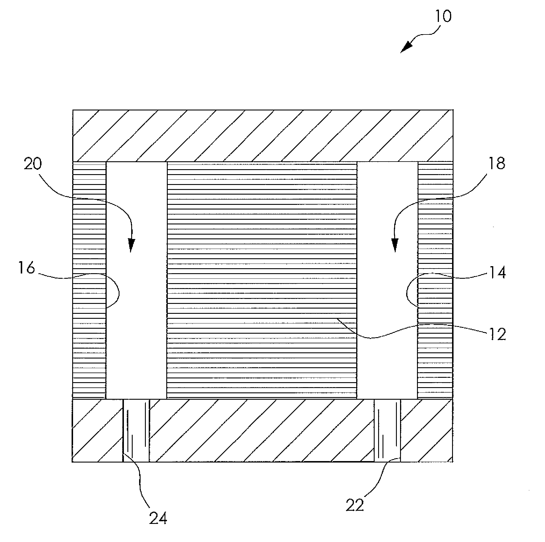
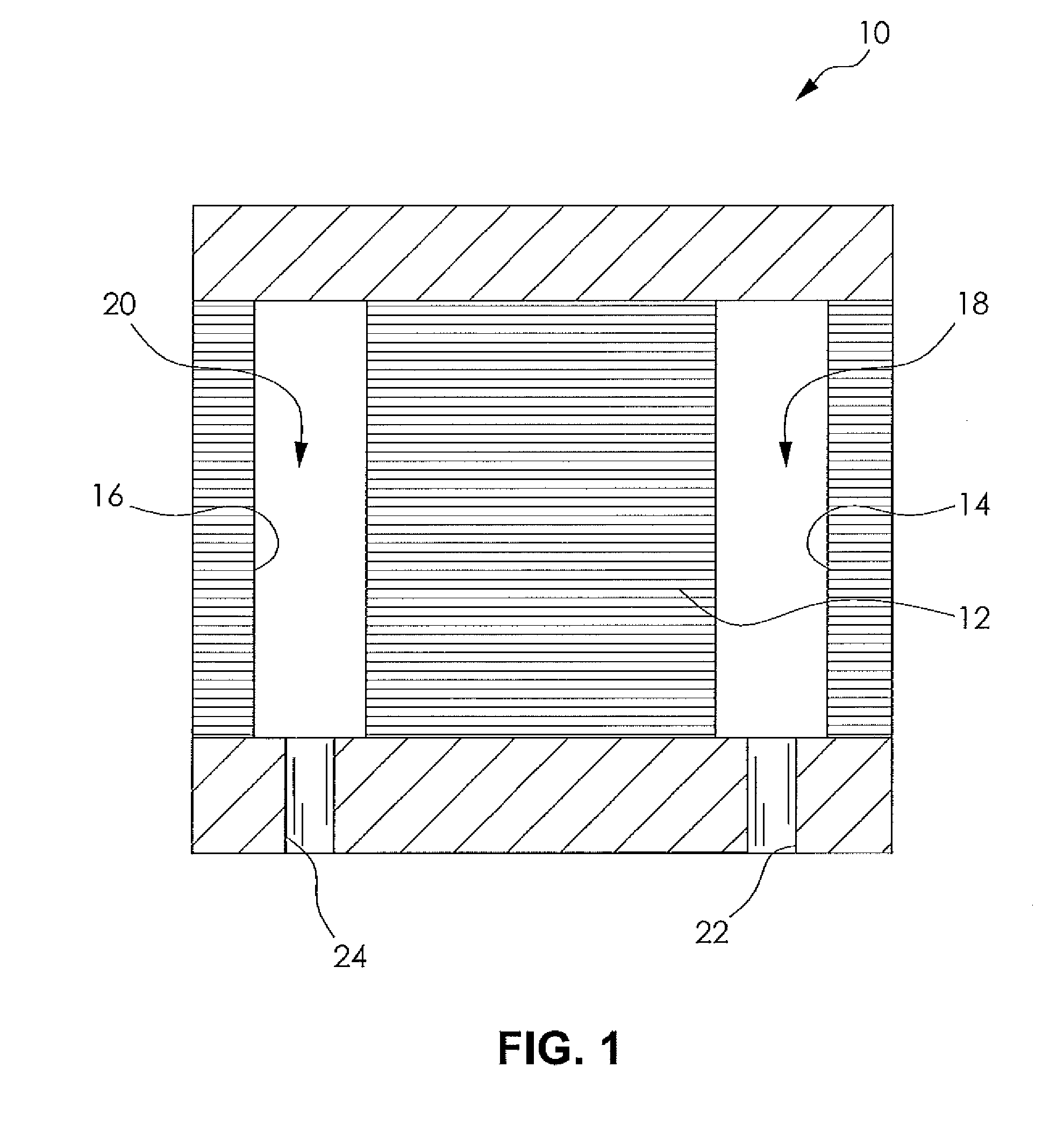
[0021]FIG. 1 shows a fuel cell assembly 10 according to an embodiment of the present disclosure. The fuel cell assembly 10 includes a plurality of stacked fuel cells 12. Each of the fuel cells 12 includes an inlet port 14 and an outlet port 16. The fuel cells 12 are stacked with the inlet port 14 and the outlet port 16 of each fuel cell 12 substantially aligned with the respective inlet port 14 and outlet port 16 of an adjacent plate or fuel cell 12. Collectively, the inlet ports 14 of each of the fuel cells 12 form an inlet header 18 and the outlet ports 16 of each of the fuel cells 12 form an outlet header 20. It is understood that the diameter, quantity, and length of the inlet header 18 will depend on the...


PUM


Abstract

A fuel cell plate for a fuel cell assembly is provided that includes a pair of unipolar plates including a flow field, an inlet flow distributor, and an outlet flow distributor, wherein the flow distributors are produced from a porous material to control liquid water throughout the reactant flow path.

Description

FIELD OF THE INVENTION[0001]The present disclosure relates to a fuel cell system and more particularly to a fuel cell system including a fuel cell plate having at least one porous flow distributor.BACKGROUND OF THE INVENTION[0002]Fuel cell power systems convert a fuel and an oxidant to electricity. One type of fuel cell power system employs a proton exchange membrane (hereinafter “PEM”) to catalytically facilitate reaction of the fuel (such as hydrogen) and the oxidant (such as air or oxygen) to generate electricity. Water is a byproduct of the electrochemical reaction. The PEM is a solid polymer electrolyte that facilitates transfer of protons from an anode electrode to a cathode electrode in each individual fuel cell of a stack of fuel cells normally deployed in a fuel cell power system.[0003]In the typical fuel cell assembly, the individual fuel cells have fuel cell plates with channels, through which various reactants and cooling fluids flow. Fuel cell plates may be unipolar, fo...

Claims


Application Information

Patent Timeline
IPC IPC(8): H01M8/04
CPCH01M8/0232Y02E60/50H01M8/2425H01M8/0234H01M8/0258H01M8/0267H01M8/241H01M8/2457H01M8/2483H01M8/04291
Inventor OWEJAN, JON P.GAGLIARDO, JEFFREY J.TRABOLD, THOMAS A.
Owner GM GLOBAL TECH OPERATIONS LLC
Why Eureka
Try Eureka