Unlock instant, AI-driven research and patent intelligence for your innovation.

Mobile communication system, mobile station device, base station device, and mobile communication method

a mobile communication system and mobile station technology, applied in the direction of wireless communication, electrical equipment, assess restriction, etc., can solve the problems of no shared channel in the dmbms cell, large amount of radio resources consumed, and the number of mobile station devices trying to perform reception, so as to improve the reception characteristics or frequency use efficiency

Inactive Publication Date: 2011-02-17
SHARP KK
View PDF13 Cites 29 Cited by
  • Summary
  • Abstract
  • Description
  • Claims
  • Application Information

AI Technical Summary

Benefits of technology

The present invention relates to a mobile communication system, a mobile device, a base station device, and a method for cell search and handover. The technical effects of the invention include increased communication rate by introducing technologies for Evolved Universal Terrestrial Radio Access (EUTRA) and a simplified cell search procedure for mobile devices in EUTRA. The invention also provides a method for handover between base station devices and a neighboring cell. The information regarding the neighboring cell is not transmitted from the base station device to the mobile device in EUTRA, so the mobile device needs to detect the synchronization channel of the neighboring cell and acquire the cell ID of the neighboring cell through a cell search procedure. The invention also includes a simplified cell search procedure for mobile devices in EUTRA.

Problems solved by technology

Therefore, the number of mobile station devices trying to perform reception is increased, and a large amount of radio resources is consumed.
However, no shared channel is used in the dMBMS cell.
Thus, this method may not be used if the list of neighboring cells is not used or if only limited information (for example, a carrier frequency) is reported.
The setup of an SCH in the dMBMS cell is being studied, but there are problems such as the following (1) to (3).(1) If there is a dMBMS cell narrowing a subcarrier interval as described above, it is necessary to receive a plurality of types of synchronization channels, and the processing load on the mobile station device is increased.(2) If the dMBMS cell narrowing the subcarrier interval uses the same subcarrier interval or sequence as that used in another unicast cell, a mobile station device trying to synchronize only an SCH (or a channel including even a channel necessary for synchronization) with the unicast cell also detects the dMBMS cell, and a delay occurs in a synchronization process.(3) In a situation where it is necessary to lengthen a CP length by considering a delay wave in the case of the above-described (2), a CP length of a synchronization channel may be the same as that of the unicast cell, and thus inter-symbol interference may occur, leading to characteristic degradation.

Method used


Image

  • Mobile communication system, mobile station device, base station device, and mobile communication method
  • Mobile communication system, mobile station device, base station device, and mobile communication method
  • Mobile communication system, mobile station device, base station device, and mobile communication method

Examples


first embodiment

[0110]First, the first embodiment of the present invention will be described. This embodiment relates to a mobile station device of an idle state.

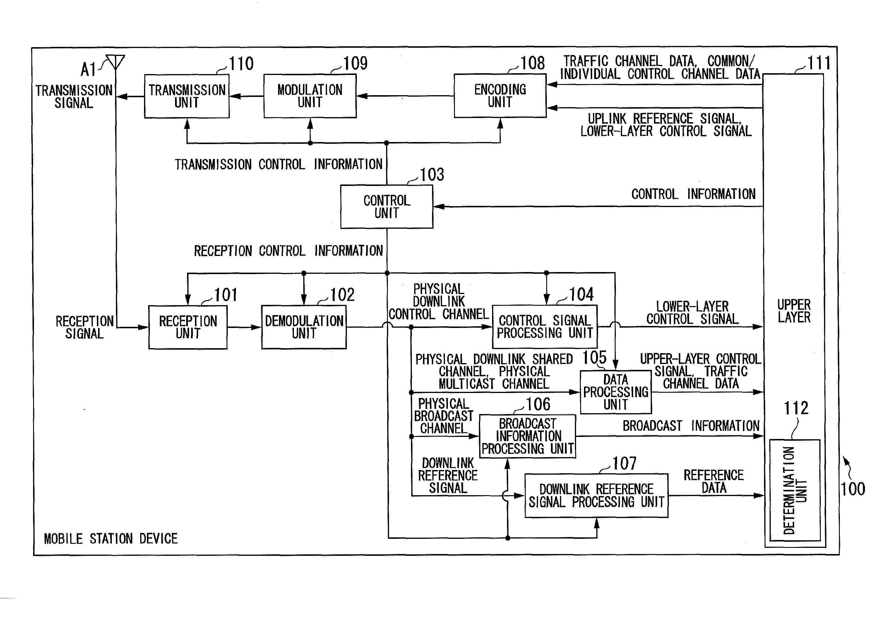
[0111]FIG. 1 is a schematic block diagram showing the configuration of the mobile station device 100 according to the first embodiment of the present invention. The mobile station device 100 includes a reception unit 101, a demodulation unit 102, a control unit 103, a control signal processing unit 104, a data processing unit 105, a broadcast information processing unit 106, a reference signal processing unit 107, an encoding unit 108, a modulation unit 109, a transmission unit 110, an upper layer 111, and an antenna A1.

[0112]Also, the upper layer 111 has a determination unit 112.

[0113]The reception unit 101 receives a signal transmitted by a base station device via the antenna A1 among signals of a frequency set based on reception control information output by the control unit 103.

[0114]The reception unit 101 performs a down-conversion pr...

second embodiment

[0198]Next, the second embodiment of the present invention will be described.

[0199]This embodiment relates to a mobile station device in an active state. Since the mobile station device and a base station device of the second embodiment of the present invention can use the same configurations as the mobile station device 100 (FIG. 1) and the base station device 200 (FIG. 3) according to the first embodiment of the present invention, a detailed description thereof is omitted.

[0200]Also, since a cell configuration according to the second embodiment of the present invention is the same as that of the first embodiment (FIG. 4), a description thereof is omitted.

[0201]FIG. 7 is a sequence diagram showing a process of the mobile communication system according to the second embodiment of the present invention. FIG. 7 shows a handover process in the mobile station device 100 in an active state.

[0202]The mobile station device 100 is in a state before the measurement of reception qualities fro...

third embodiment

[0279]Next, the third embodiment of the present invention will be described. In the second embodiment, the case where a handover process is performed after the base station device determines the presence / absence of provision of the MBMS service for a neighboring cell for which the mobile station device 100 measures reception quality will be described.

[0280]In the third embodiment, a cell ID of a neighboring cell for which measurement is performed is reported in advance from the base station device to the mobile station device 100. The mobile station device 100 measures and reports only the reception quality of the neighboring cell reported from the base station device.

[0281]Since the mobile station device 100 (FIG. 1) or the base station device 200 (FIG. 3) described in the first embodiment may be used as the mobile station device or the base station device used in this embodiment, a detailed description thereof is omitted.

[0282]Since a cell configuration used in this embodiment is ...


PUM


Abstract

A mobile communication system including a mobile station device and a base station device, wherein the mobile station device includes: a reception quality measurement unit which measures reception qualities based on signals transmitted from neighboring base station devices; a determination unit which determines a base station device with which the mobile station device communicates, based on a service tried to receive by the mobile station device and the reception qualities measured by the reception quality measurement unit; and a communication unit which communicates with the base station device determined by the determination unit.

Description

TECHNICAL FIELD[0001]The present invention relates to a mobile communication system, a mobile station device, a base station device, and a mobile communication method.[0002]This application claims priority from and the benefits of Japanese Patent Application No. 2008-117758 filed on Apr. 28, 2008, the disclosure of which is incorporated herein by reference.BACKGROUND ART[0003]At present, Evolved Universal Terrestrial Radio Access (EUTRA) is being studied by the standardization body 3rd Generation Partnership Project (3GPP) (Non-Patent Document 1).[0004]The purpose of EUTRA is to increase the communication rate by introducing some of the technologies which are being studied for a fourth generation system in a third-generation frequency band.[0005]An orthogonal frequency division multiplexing access (OFDMA) scheme is used as a communication scheme in EUTRA. OFDMA is a communication scheme robust against multipath interference and suitable for high-speed transmission.[0006]In relation ...

Claims


Application Information

Patent Timeline
Patent Type & Authority Applications(United States)
IPC IPC(8): H04W24/00H04W36/00
CPCH04W48/20
Inventor TSUBOI, HIDEKAZUUEMURA, KATSUNARI
Owner SHARP KK