Method and System for Decoding Graph-Based Codes Using Message-Passing with Difference-Map Dynamics

a graph-based code and message-passing technology, applied in the field of decoding graph-based codes, can solve the problems of significant error floor, low error rate of decoders, and inability to achieve the same in the high-snr regime, and achieve the effect of improving the error floor

Inactive Publication Date: 2011-02-17
MITSUBISHI ELECTRIC RES LAB INC
View PDF16 Cites 30 Cited by
  • Summary
  • Abstract
  • Description
  • Claims
  • Application Information

AI Technical Summary

Benefits of technology

[0033]Another embodiment of the BP decoder uses updating rules that are similar to the standard “min-sum” or “sum-product” BP decoder but with important alterations based on the “difference map” (DM) idea from the Divide and Concur m

Problems solved by technology

Problems with Standard BP Decoders of LDPC Codes
Unfortunately, the factor graphs for good codes invariably contain cycles, and in the presence of cycles, the min-sum BP decoder becomes sub-optimal.
Sub-optimal sum-product BP decoders nevertheless achieve near Shannon limit performance for good graph-based codes in the waterfall regime, but unfortunately, the same is not true in the high-SNR regime.
In the high-SNR regime graph-based codes paired with sum-product or min-sum BP decoders often suffer from an “error floor” phenomena, whereby the decoder error rate improves only slowly as the SNR increases.
The error floor is a significant problem for applications that require extremely high reliability for high bit densities and data rates.
It limits the applicability of current generation graph-based codes in such applications, which include magneto-optic data storage, and fiber-optic communications.
Error patterns resulting from channel transmission that strongly overlap these patterns are uncorrectable by the decoder.
However, for many applications, specified codes, or codes of specified blocklengths and rates, may be required, and this approa

Method used


Image

  • Method and System for Decoding Graph-Based Codes Using Message-Passing with Difference-Map Dynamics
  • Method and System for Decoding Graph-Based Codes Using Message-Passing with Difference-Map Dynamics
  • Method and System for Decoding Graph-Based Codes Using Message-Passing with Difference-Map Dynamics

Examples


Embodiment Construction

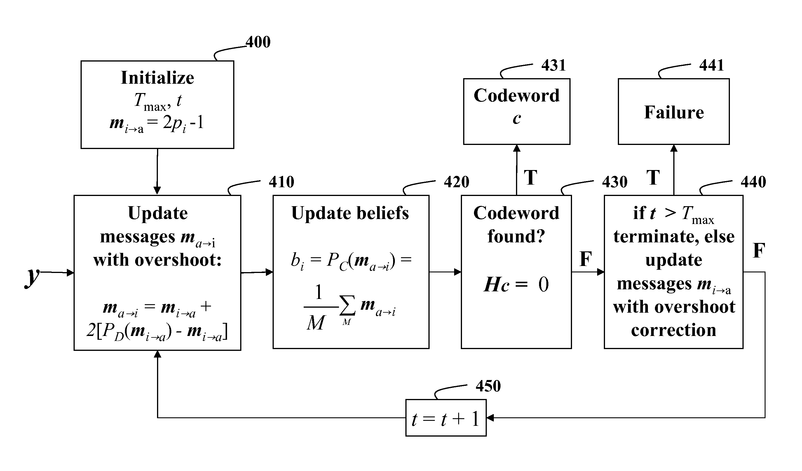
[0039]The embodiments of our invention provide methods for decoding graph-based codes, including low-density parity check (LDPC) codes, using novel belief propagation (BP) decoders. The codes can be used to store and communicate data. More specifically, our invention is well suited for high-density storage, and high data rates, such as magneto-optic storage media, and fiber-optic communication systems.

[0040]Because we have done extensive work on LDPC codes and BP decoders, see U.S. Pat. Nos. and Publications 7,376,173, 7,373,585, 7,191,376, 7,103,825, 7,103,818, 6,857,097, 6,771,197, 20080316069, 20080235515, 20080052594, 20070217432, 20070174633, 20060123241, 20060048038, and numerous scientific papers, we were intrigued whether any of the principles of the D&C method could be applied to LDPC codes and BP decoders. We note that there is nothing in the conventional D&C method that anticipates the elements of the BP decoders of our invention.

[0041]We were particularly curious whether...


PUM


Abstract

A code to be decoded by message-passing is represented by a factor graph. The factor graph includes variable nodes indexed by i and constraint nodes indexed by a connected by edges for transferring messages mi→a outgoing from the variable nodes to the constraint nodes and messages ma→i incoming from the constraint nodes to the variable nodes. The messages mi→a are initialized based on beliefs bi of a received codeword. The messages ma→i are generated by overshooting the messages mi→a at the constraint nodes. The beliefs bi are updated at the variable nodes using the messages ma→i. The codeword is outputted if found, otherwise, the messages mi→a are updated using a correction for the overshooting.

Description

FIELD OF THE INVENTION[0001]This invention relates generally to decoders, and more particularly to decoding graph-based codes, including low-density parity-check (LDPC) codes, using message-passing decoders.BACKGROUND OF THE INVENTION[0002]Problems with Standard BP Decoders of LDPC Codes[0003]Properly designed low-density parity-check (LDPC) codes, when decoded using belief propagation (BP) decoders, can achieve near Shannon limit performance in the so-called “water-fall” regime where the signal-to-noise ratio (SNR) is near the code threshold. Numerous BP decoders are known in the prior art. The U.S. Patent Database reveals over 500 hundred related patents and applications.[0004]Prior art BP decoders are instances of message-passing methods that operate on a graphical representation known as a “factor graph,” see F. R. Kschischang, B. J. Frey, and H.-A. Loeliger, “Factor Graphs and the Sum-Product Algorithm,” IEEE Transactions on Information Theory, vol. 47, pp. 498-519, 2001. BP de...

Claims


Application Information

Patent Timeline
IPC IPC(8): H03M13/05G06F11/10
CPCG06F7/5057G06F7/5443H04L2209/46H04L9/3218H04B10/6165H04L2209/50H03M13/1111H03M13/658
Inventor YEDIDIA, JONATHAN S.WANG, YIGEDRAPER, STARK C.
Owner MITSUBISHI ELECTRIC RES LAB INC
Why Eureka
Try Eureka