Energy system for dwelling support

a technology of energy system and support structure, which is applied in the direction of gaseous engine fuel, domestic heating, machines/engines, etc., can solve the problems of low efficiency of photosynthesis-based biomass, inability to meet demand, and inefficient current practices for producing electricity from fossil and nuclear-fueled central power plants, etc., to achieve high electricity production cost and energy saving

Active Publication Date: 2011-02-24
MCALISTER TECH LLC +1
View PDF108 Cites 57 Cited by
  • Summary
  • Abstract
  • Description
  • Claims
  • Application Information

AI Technical Summary

Problems solved by technology

Present practices for producing electricity from fossil and nuclear fueled central power plants are very inefficient.
Biomass produced by photosynthesis is less than 1% efficient and only a small amount of biomass became anaerobically processed in geological circumstances that resulted in preservation of fossil fuels.
Natural gas production has failed to keep pace with demand that has shifted from oil.
It would require more than 1,600 nuclear power plants to produce the 95 Quads of energy now consumed yearly by the U.S. Nuclear power is not a viable option.
Most of the world's population is deprived of the standard of living typical in the U.S. because of the high cost of electricity production, water heating, and air conditioning as provided by central power plants, liquefied petroleum or oil fired water heaters, and electric powered air conditioners.
Considerable loss of food value or contamination results from attack by rodents, bugs and inappropriate food preservation practices and causes disease and malnutrition.
These problems have proven to be extremely difficult to solve.
It is immoral to accept the hardships that will follow without a sustainable economy.

Method used


Image

  • Energy system for dwelling support
  • Energy system for dwelling support
  • Energy system for dwelling support

Examples


Embodiment Construction

[0018]The present application incorporates by reference in its entirety the subject matter of U.S. Provisional Patent Application No. 60 / 626,021, filed Nov. 9, 2004 and titled MULTIFUEL STORAGE, METERING AND IGNITION SYSTEM (Attorney Docket No. 69545-8013US). The present application incorporates by reference in their entirety the subject matter of each of the following U.S. patent applications, filed concurrently herewith on Aug. 16, 2010 and titled: METHODS AND APPARATUSES FOR DETECTION OF PROPERTIES OF FLUID CONVEYANCE SYSTEMS (Attorney Docket No. 69545-8003US); COMPREHENSIVE COST MODELING OF AUTOGENOUS SYSTEMS AND PROCESSES FOR THE PRODUCTION OF ENERGY, MATERIAL RESOURCES AND NUTRIENT REGIMES (Attorney Docket No. 69545-8025US); ELECTROLYTIC CELL AND METHOD OF USE THEREOF (Attorney Docket No. 69545-8026US); SUSTAINABLE ECONOMIC DEVELOPMENT THROUGH INTEGRATED PRODUCTION OF RENEWABLE ENERGY, MATERIALS RESOURCES, AND NUTRIENT REGIMES (Attorney Docket No. 69545-8040US); SYSTEMS AND ME...


PUM


Abstract

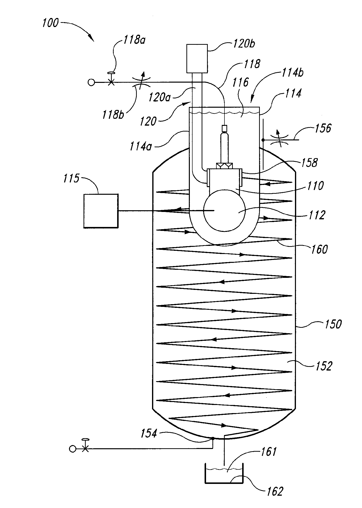
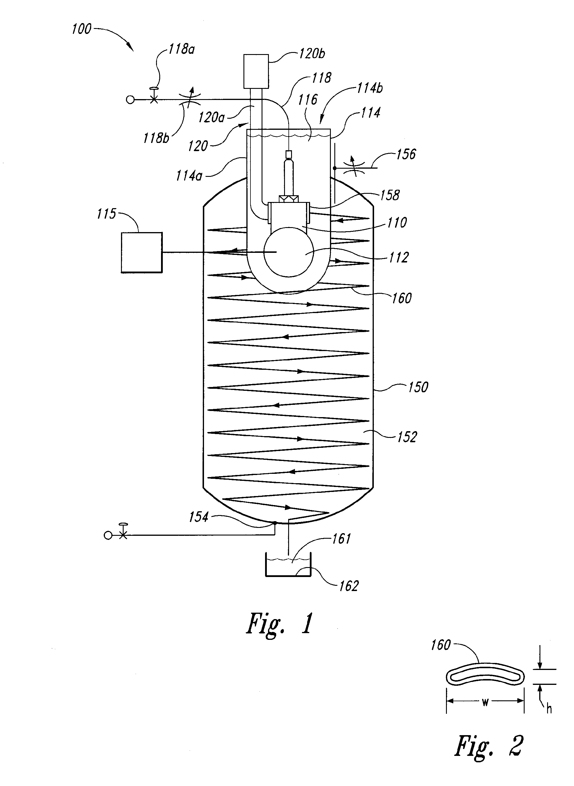
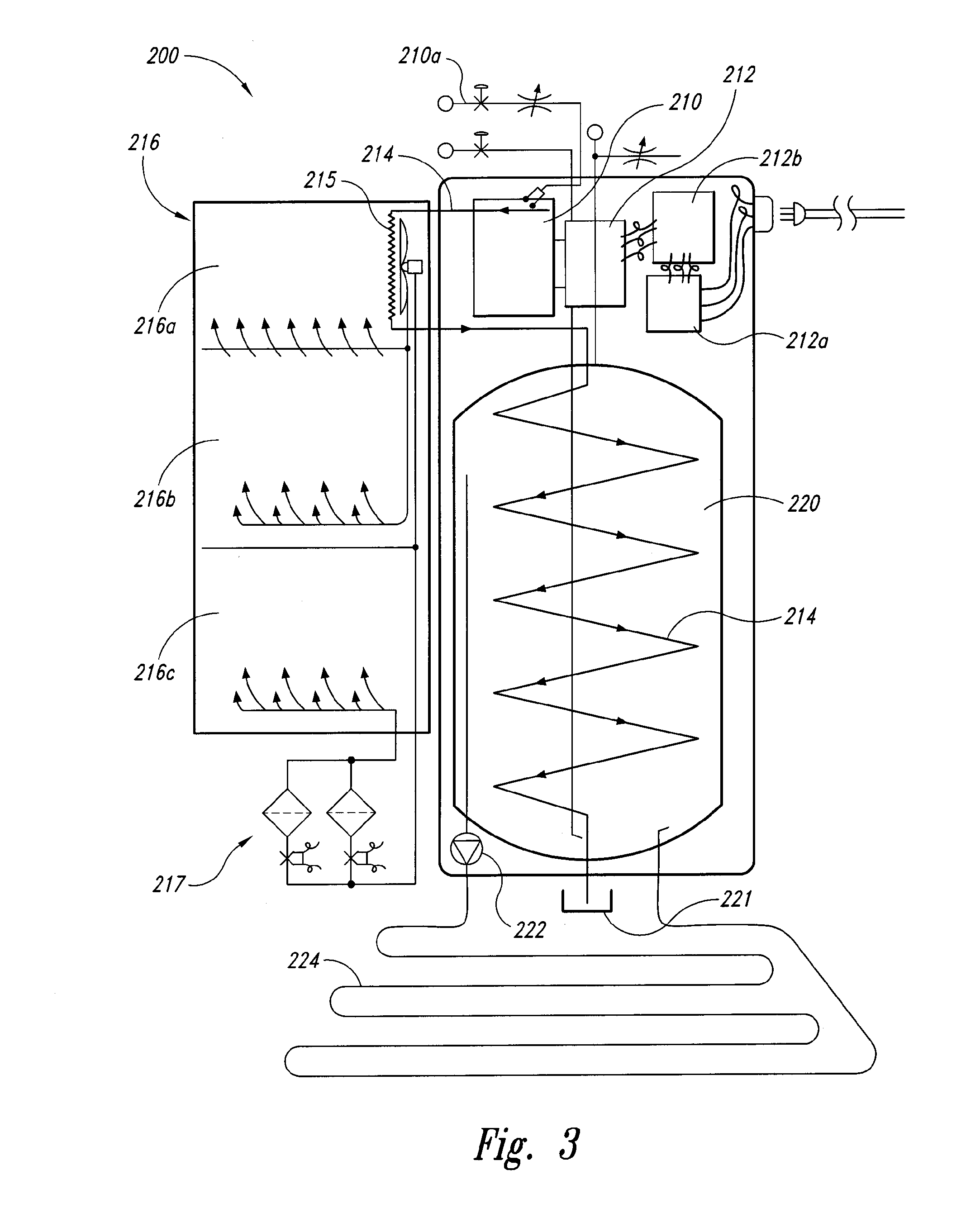
The present disclosure is directed to a system and method of providing energy to a dwelling. An engine is housed within an inner tank, which is in turn housed within an outer tank. The engine provides electricity which is used for a dwelling. Exhaust fumes from the engine are piped through a series of heat-exchanging tubes within the outer tank to heat potable water within the outer tank. Water enters the potable tank at a bottom of the tank, and warms as it rises through the outer tank toward an outlet near a top of the outer tank. Hot, potable water is provided from the top of the outer tank to the dwelling. Condensate from the exhaust is captured and used as potable water. Heat, vibration, and acoustic energy from the engine is captured by the fluid in the inner tank and transferred to the outer tank.

Description

CROSS-REFERENCE TO RELATED APPLICATION[0001]The present application claims priority to and the benefit of U.S. Provisional Application No. 61 / 304,403, filed Feb. 13, 2010 and titled FULL SPECTRUM ENERGY AND RESOURCE INDEPENDENCE. The present application is a continuation-in-part of each of the following applications: U.S. patent application Ser. No. 12 / 707,651, filed Feb. 17, 2010 and titled ELECTROLYTIC CELL AND METHOD OF USE THEREOF; PCT Application No. PCT / US10 / 24497, filed Feb. 17, 2010 and titled ELECTROLYTIC CELL AND METHOD OF USE THEREOF; U.S. patent application Ser. No. 12 / 707,653, filed Feb. 17, 2010 and titled APPARATUS AND METHOD FOR CONTROLLING NUCLEATION DURING ELECTROLYSIS; PCT Application No. PCT / US10 / 24498, filed Feb. 17, 2010 and titled APPARATUS AND METHOD FOR CONTROLLING NUCLEATION DURING ELECTROLYSIS; U.S. patent application Ser. No. 12 / 707,656, filed Feb. 17, 2010 and titled APPARATUS AND METHOD FOR GAS CAPTURE DURING ELECTROLYSIS; and PCT Application No. PCT / US...

Claims


Application Information

Patent Timeline
Patent Type & Authority Applications(United States)
IPC IPC(8): F02B63/04F01N5/02
CPCY02T10/16F01N5/02C25B1/00C25B1/02C25B3/00C25B13/02C25B15/00C25B9/17F02G5/04F24D11/005F24D2200/26F24D2200/29F24D2200/30F28D7/103F24S20/20Y02E10/40Y02T10/12
Inventor MCALISTER, ROY E.
Owner MCALISTER TECH LLC
Why Eureka
Try Eureka