
Circuit for preventing self-heating of metal-insulator-transition (MIT) device and method of fabricating integrated-device for the same circuit

a technology of metal-insulator-transition and mit, which is applied in the field of circuits, can solve the problems of malfunction of current driving devices, high possibility of self-heating phenomenon described above, and inability to manufacture integrated devices for the same circui

Active Publication Date: 2011-02-24
ELECTRONICS & TELECOMM RES INST
View PDF12 Cites 11 Cited by
  • Summary
  • Abstract
  • Description
  • Claims
  • Application Information

AI Technical Summary

Benefits of technology

[0022]The present invention also provides a current control circuit including: a metal-insulator transition (MIT)-transistor comprising a MIT device generating an abrupt metal-insulator transition at a temperature equal to or greater than a critical temperature and a control transistor connected to the MIT device; and at least one power transistor that is connected to a current driving device to supply power to the current driving device and to control the power to the current driving device, wherein the MIT-transistor is attached to a surface of the power transistor or a heating portion of the power transistor, and is connected to a base electrode, a gate electrode, a collector electrode, or a drain electrode of the power transistor, and when the temperature of the power transistor increases, the MIT-transistor reduces or cuts a current of the power transistor to prevent heating of the power transistor.

Problems solved by technology

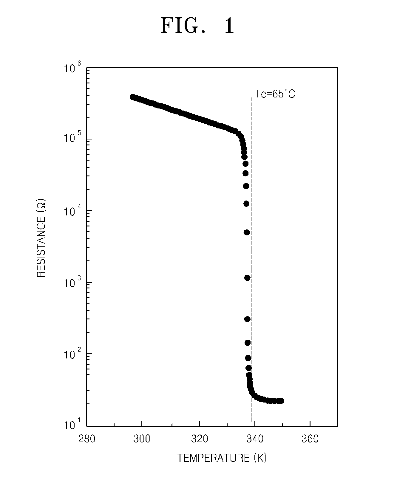
The self-heating interferes a switching operation or causes failures of the switching operation of the MIT device, and thus, eventually causes a malfunction of a current driving device.
If an over-current is applied to the MIT device or malfunctions occur in the current driving device, there is a high possibility that the self-heating phenomenon described above can occur in the MIT device.
Since the MIT device is not yet commercialized, the self-heating of the MIT device is not well known.
However, the self-heating of the MIT device is still as an unsolved problem in the fields of studying the MIT device and its application.

Method used


Image

  • Circuit for preventing self-heating of metal-insulator-transition (MIT) device and method of fabricating integrated-device for the same circuit
  • Circuit for preventing self-heating of metal-insulator-transition (MIT) device and method of fabricating integrated-device for the same circuit
  • Circuit for preventing self-heating of metal-insulator-transition (MIT) device and method of fabricating integrated-device for the same circuit

Examples


Embodiment Construction

[0039]The present invention will now be described more fully with reference to the accompanying drawings, in which exemplary embodiments of the invention are shown. The present invention may, however, be embodied in many different forms and should not be construed as being limited to the embodiments set forth herein; rather, these embodiments are provided so that this disclosure will be thorough and complete, and will fully convey the concept of the invention to one skilled in the art. It will also be understood that when a layer is referred to as being “on” another layer or substrate, it can be directly on the other layer or substrate, or intervening layers may also be present. In the drawings, the thicknesses of layers and regions are exaggerated for clarity and portions nothing to do with the description are omitted. Like reference numerals in the drawings denote like elements, and thus their description will be omitted. The terminology used herein is for the purpose of describin...


PUM


Abstract

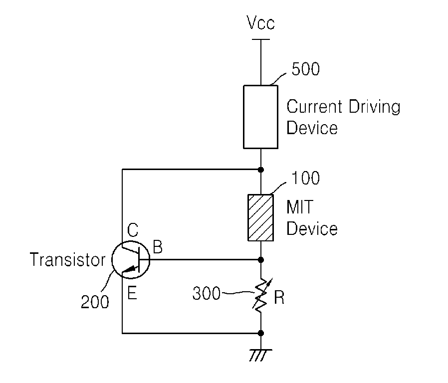
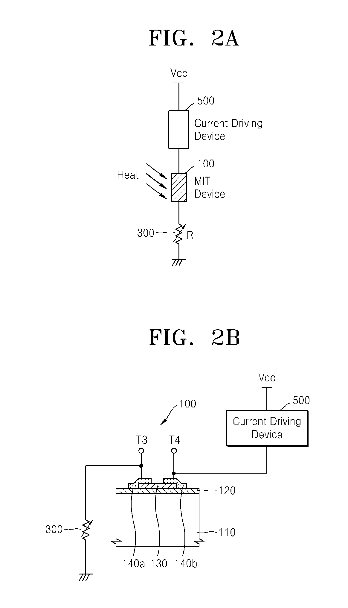
Provided are a MIT device self-heating preventive-circuit that can solve a self-heating problem of a MIT device and a method of manufacturing a MIT device self-heating preventive-circuit integrated device. The MIT device self-heating preventive-circuit includes a MIT device that generates an abrupt MIT at a temperature equal to or greater than a critical temperature and is connected to a current driving device to control the flow of current in the current driving device, a transistor that is connected to the MIT device to control the self-heating of the MIT device after generating the MIT in the MIT device, and a resistor connected to the MIT device and the transistor.

Description

CROSS-REFERENCE TO RELATED PATENT APPLICATION[0001]This application claims the benefits of Korean Patent Application No. 10-2008-0016935, filed on Feb. 25, 2008, No. 10-2008-0091265, filed on Sep. 17, 2008, and No. 10-2009-0002732, filed on Jan. 13, 2009, in the Korean Intellectual Property Office, the disclosures of which are incorporated herein in their entirely by reference.BACKGROUND OF THE INVENTION[0002]1. Field of the Invention[0003]The present invention relates to a Metal-Insulator-Transition (MIT) device, and more particularly, to a circuit for preventing a MIT device from self-heating and a method of fabricating an integrated device in which the circuit is integrated.[0004]2. Description of the Related Art[0005]A Metal-Insulator-Transition (MIT) device generates a metal-insulator-transition (MIT) phenomenon in which an insulator transits to a metal or a metal transits to an insulator according to various physical characteristics such as voltage, electric field, electromagn...

Claims


Application Information

Patent Timeline
Patent Type & Authority Applications(United States)
IPC IPC(8): H05B37/02H01L21/8222H01L21/8234H03K3/011H10N97/00H10N99/00
CPCH01L49/003H01L27/067H10B63/00H10N70/823H10N70/20H10N70/8833H01L29/73G05F3/24H10N99/03
Inventor KIM, HYUN-TAKKIM, BONG-JUNYUN, SUN-JINKIM, DAE-YONG
Owner ELECTRONICS & TELECOMM RES INST
Learn More