
Calibration of linear time-invariant system's step response

a linear time-invariant system and step response technology, applied in the direction of resistance/reactance/impedence, pulse automatic control, negative-feedback-circuit arrangement, etc., can solve the problems of linear time-invariant system stability, loop gain and bandwidth are high, and stability problems occur

Active Publication Date: 2011-02-24
NXP BV
View PDF6 Cites 8 Cited by
  • Summary
  • Abstract
  • Description
  • Claims
  • Application Information

AI Technical Summary

Benefits of technology

[0008]Accordingly, it is an object of the present invention to provide a method and an implementation, which enables calibration of linear time-invariant systems, e.g. a feedback amplifier with potential risk of in-stability.
[0029]By measuring the response to a small step-shaped signal as function of time at the input of a linear time-invariant system, internal stabilizing components can be adapted “on-the-fly” in order to create more phase margin, if needed. In other words: an optimization of the design of an amplifier for each situation, supply, process and temperature conditions is possible.

Problems solved by technology

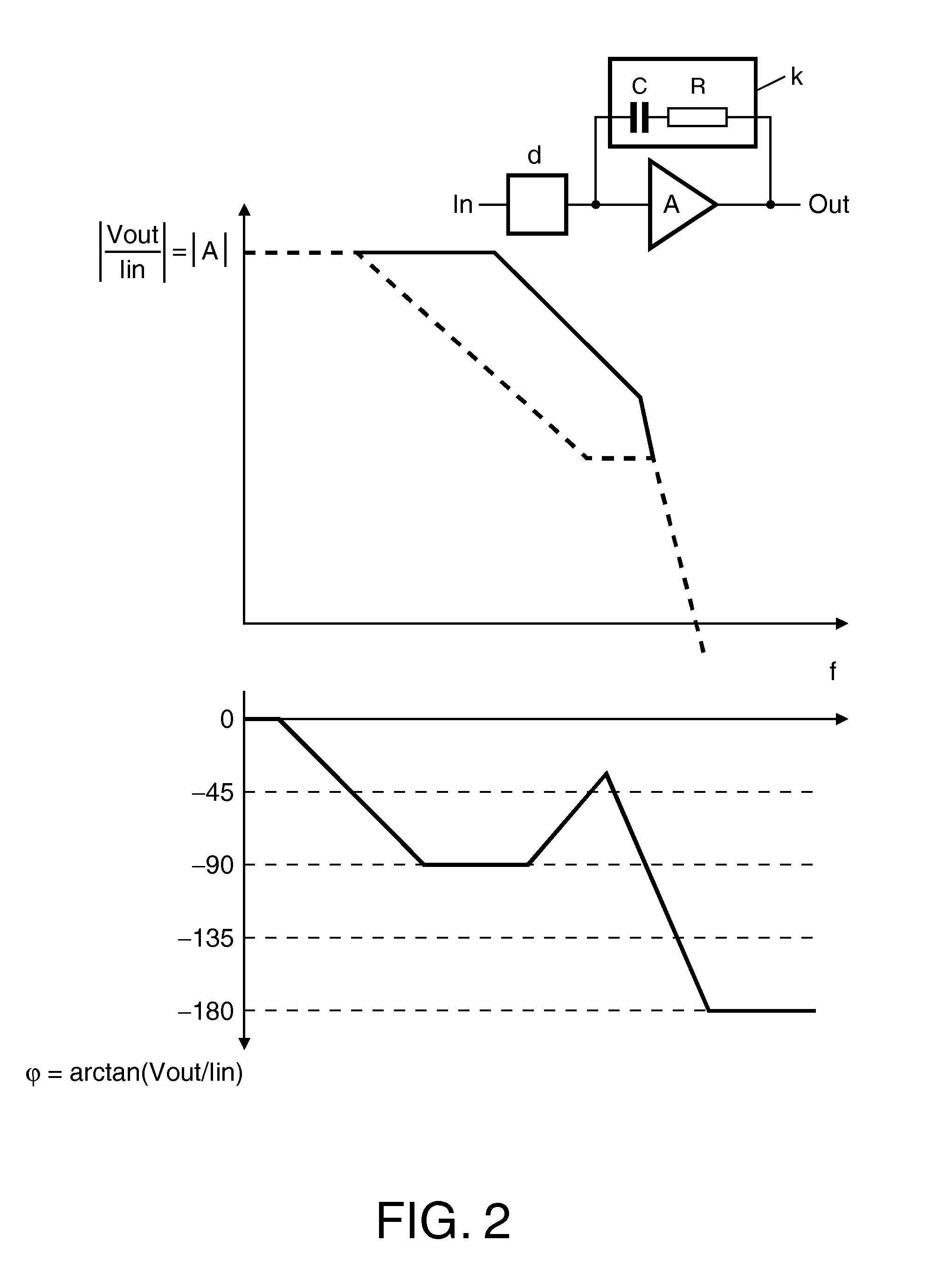
Stability of linear time-invariant systems, such as low noise amplifiers (LNA's) or intermediate frequency amplifiers (IFAMPS) just to name two examples, can be a serious issue when large linearity is required and therefore both loop gain and bandwidth are high.
However, stability problems occur when the phase of the loop-transfer function, in combination with unity loop-gain, becomes 180°.
However, U.S. Pat. No. 6,232,834 does not provide how the response of circuits operated at high frequencies can be measured.
This means that often circuits don't perform in their optimum because possible process and mismatch dictate less optimal bias conditions.

Method used


Image

  • Calibration of linear time-invariant system's step response
  • Calibration of linear time-invariant system's step response
  • Calibration of linear time-invariant system's step response

Examples


first embodiment

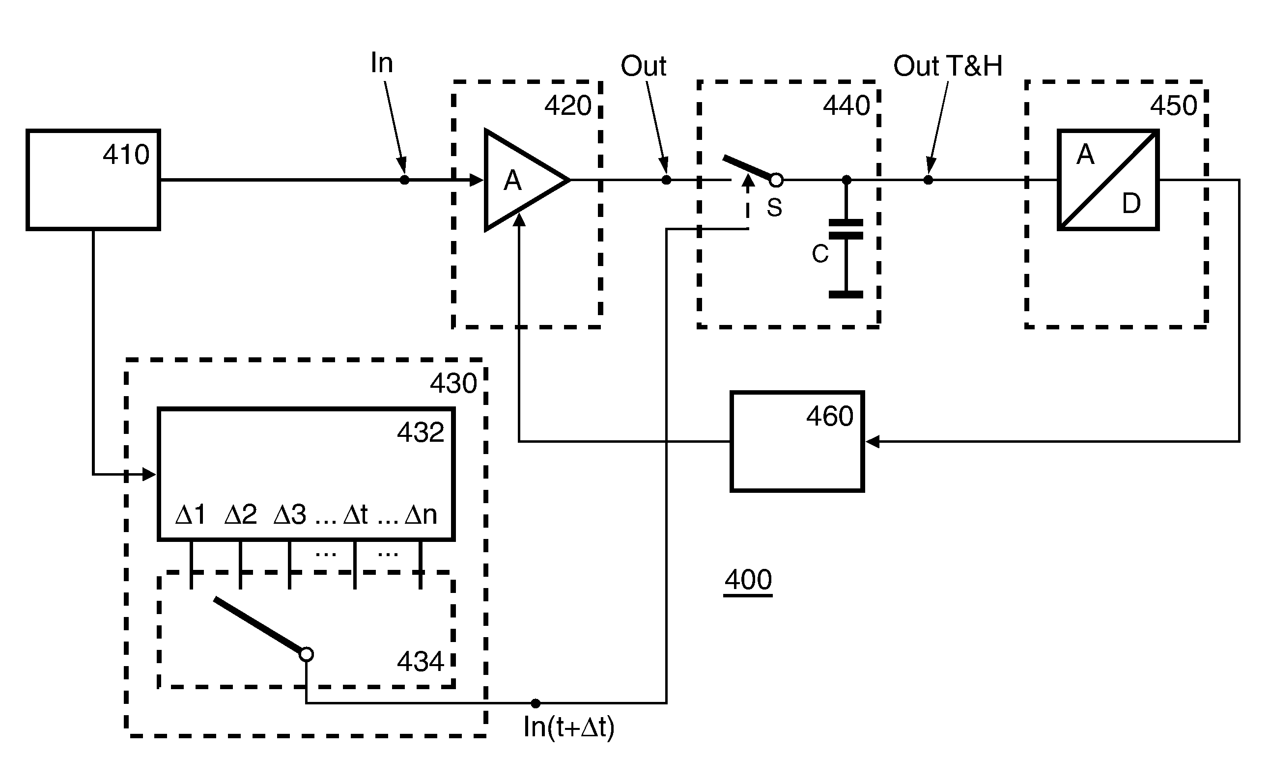
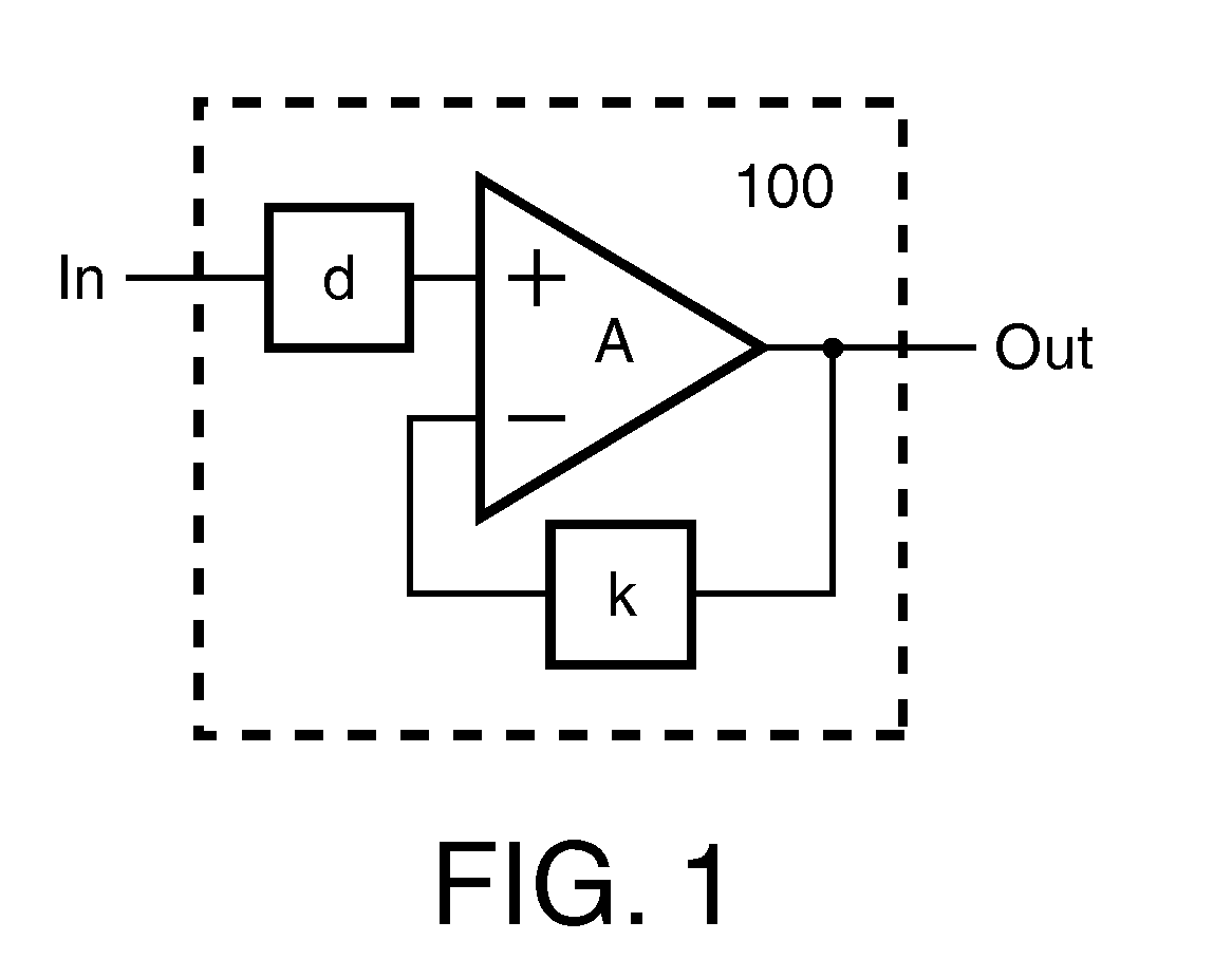
[0045]Now with reference to FIG. 4, which shows a calibration circuit arrangement 400 for a fast step response of a linear time-invariant system according to the invention. Test signal means 410 for generating a step signal as test signal are provided, for which e.g. a Square Wave Signal Generator (SWSG) can be used. The output of the test signal means 410 is connected to the input (In) of a device under test (DUT) 420, which can be an amplifier circuit arrangement as illustrated in FIG. 1. Accordingly, the DUT A is excited by the test signal from the SWSG.

[0046]Further, the output of the test signal means 410 is connected to delay means 430, where the test signal is used to trigger or switch respective delay-elements, e.g. delay lines. Thus, the actual test signal is provided at the output of delay means 430 with a respective delay. The delay means 430 can be implemented be a bank of delay-lines 432, where a particular output is selected by means of a multiplexer 434. It goes witho...

second embodiment

[0053]The inventors found that the afore-described concept holds for every linear time-invariant system. Also slow responding systems can be calibrated, where the delay means 430 are not needed. An arrangement applicable for calibration of a slow system is shown in FIG. 6, which shows a calibration circuit arrangement 600 for measuring a slow step response of a linear time-invariant system 425 according to the invention. Such a slow system 425 can be e.g. an intermediate frequency (IF) filter. However, it will be appreciated that the proposed solution may also be applicable in complex technical systems such as a beer-brewery system or a petrochemical system. Accordingly, applications for calibration of linear time-invariant systems as being proposed are amplifiers and filters in electronic circuits, but also process-control applications that are widely used in e.g. petrochemical industry, food industry and robot industry.

[0054]In FIG. 6, the linear time invariant system 425 is excit...


PUM


Abstract

The invention concerns in general measurement of the transfer function of linear time invariant systems, more particular the calibration of such systems based on a measured transfer function. According to a first aspect the present invention an arrangement for measuring the transfer function of a linear time-invariant system is disclosed. According to a second aspect of the present invention the arrangement is implemented into a linear time-invariant circuitry having a transfer function representing the amplitude and phase characteristic of the circuitry, where by means of the arrangement for measuring the transfer function the transfer function can be optimized in accordance with certain criteria on-the-fly, i.e. in or before operation of the circuit. Finally, an effective and simple method for measuring of the transfer function of a linear time-invariant system together with the use or application of the method is shown.

Description

FIELD OF THE INVENTION[0001]The present invention relates in general to the measurement of the transfer function of linear time invariant systems and weakly non-linear time invariant systems. In particular the present invention relates to the calibration of such systems based on a measured transfer function thereof.[0002]According to a first aspect the present invention relates to an arrangement for measuring the transfer function of a linear time-invariant system. According to a second aspect the present invention relates to a linear time-invariant circuitry having a transfer function representing the amplitude and phase characteristic of the circuitry, in which the arrangement for measuring the transfer function can be implemented. Jet another aspect of the invention relates to a method for measuring of the transfer function of a linear time-invariant system. A last aspect of the invention concerns the use or application the method.BACKGROUND OF THE INVENTION[0003]Stability of lin...

Claims


Application Information

Patent Timeline
IPC IPC(8): H03F1/34G01R27/28
CPCG01R31/2837
Inventor JEURISSEN, DENNISDE JONG, GERBEN WILLEMVAN SINDEREN, JAN
Owner NXP BV
Learn More