Al technical title is built by PatSnap Al team. It summarizes the technical point description of the patent document.
a technology of optical fiber and assembly, applied in the field of optical fiber connection assembly, can solve the problems of optical fiber end, optical fiber misalignment, transmission loss, etc., and achieve the effect of reducing or minimizing air gap, precise torque control, and avoiding loss
Inactive Publication Date: 2011-02-24
DIBA IND
View PDF28 Cites 4 Cited by
Summary
Abstract
Description
Claims
Application Information
AI Technical Summary
This helps you quickly interpret patents by identifying the three key elements:
Problems solved by technology
Method used
Benefits of technology
[0005]It is against the above background that embodiments of the present invention provide an optical fiber connection assembly with a torque-limiting feature to facilitate the connecting of ends of the optical fibers through assuring proper alignment and sufficient proximity of the transmitting and receiving ends of the optical fibers so as to minimize light transmission loss.
[0006]Embodiments of the present invention generally relate to an optical fiber connection assembly comprising a torque fitting and a fitting connector. The optical fiber connection assembly aligns optical fibers along an optical path in a proximity sufficient to permit transmission of light across the optical fibers with achievement of a threshold level of torque applied in releasably connecting the torque fitting to the fitting connector. More particularly, embodiments of the present invention generally align optical fibers along an optical path in a proximity sufficient to permit transmission of light across the optical fibers with minimal transmission loss. A torque-limiting configuration of the torque fitting prevents an over-tightening and avoids an under-tightening of the torque fitting releasably connected to the fitting connector. Embodiments of the present invention also generally relates to methods of aligning optical fibers with a torque fitting and a fitting connector for a transmission of light across the optical fibers.
Problems solved by technology
Transmission loss generally is attributed to misalignment of optical fibers, damage to ends of the optical fibers, and / or the presence of a gap between the transmitting and receiving ends of the optical fibers.
Connectors used to connect optical fibers frequently cause or further exacerbate these conditions leading to greater transmission loss.
With the presence of a significant gap between the optical fibers, an emerging cone of light from the transmitting end spills over the optical core of the receiving fiber and is lost.
In addition, an air gap between the optical fibers may cause a reflection when the transmitted light encounters the change in refractive index from the glass of the optical fiber to the air in the gap.
This reflection generally amounts to about 5% of the transmitted light in typical flat polished optical fiber connectors, typically resulting in transmission loss of greater than 0.3 decibels per kilometer.
Method used
Image
Click on the blue label to locate the original text in one second.
Reading with bidirectional positioning of images and text.
Examples
Embodiment Construction
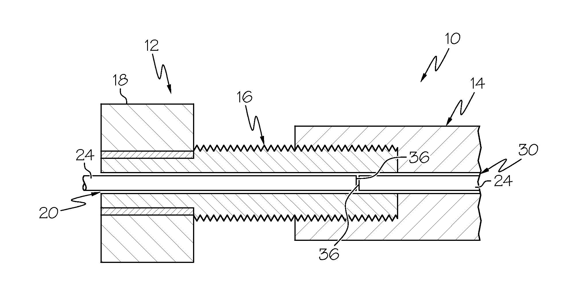
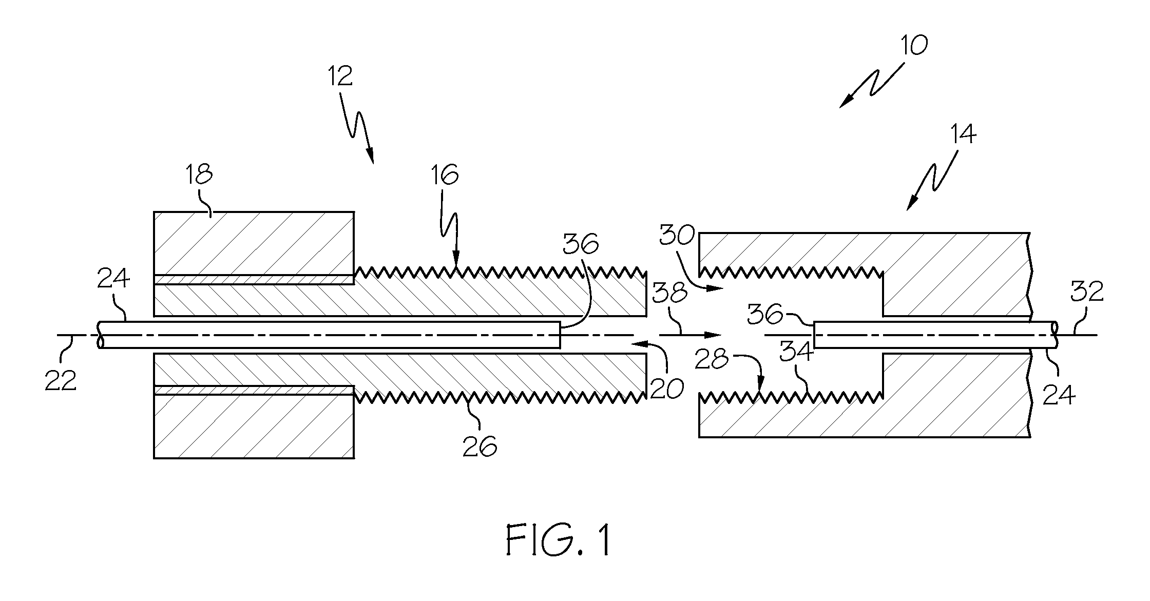
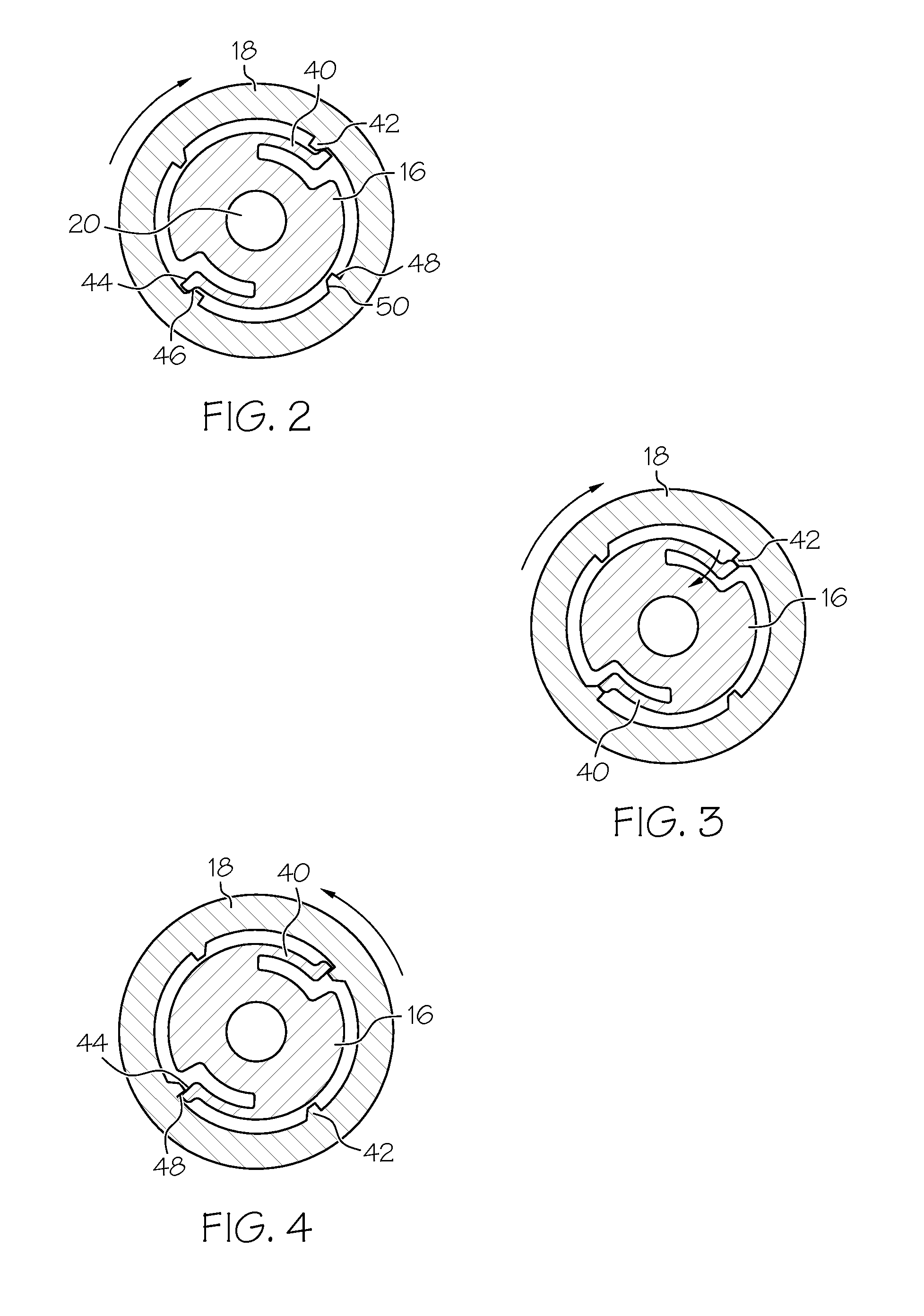
[0019]The optical fiber connection assembly is configured to align ends of optical fibers along an optical path for a transmission of light across the optical fibers. Referring initially to FIG. 1, the optical fiber connection assembly 10 comprises a torque fitting 12 and a fitting connector 14. The torque fitting 12 comprises a threaded body portion 16, a torque-limiting body portion 18, and an optical fiber accommodating channel 20. The threaded body portion 16 and the torque-limiting body portion 18 are arranged substantially concentrically along a longitudinal axis 22 of the torque fitting 12. The channel 20 is oriented along this longitudinal axis 22, extends through opposite ends of the torque fitting 12, and defines a cross-sectional area sufficient to accommodate an optical fiber 24. The threaded body portion 16 comprises a mechanical thread 26. The mechanical thread 26 defines a compressive direction of rotation, as shown by the clockwise directional arrow depicted in FIGS....
PUM
Abstract
Optical fiber connection assemblies respectively comprising a torque fitting and a fitting connector are described. The torque fitting comprises a torque-limiting body portion, a threaded body portion with a mechanical thread, and an optical fiber accommodating channel. The fitting connector, meanwhile, comprises threaded body portion with a mechanical thread complimentary to that of the torque fitting. The respective threaded body portions releasably connect via the complimentary mechanical threads by rotating the threaded body portion of the torque fitting along the threaded body portion of the fitting connector the such that optical fibers accommodated by the respective channels are aligned along an optical path in a proximity sufficient to permit transmission of light across the optical fibers with achievement of the threshold level of torque applied in rotating the torque fitting in the compressive direction of rotation along the threaded body portion of the fitting connector. Additional embodiments are disclosed and claimed.
Description
CROSS-REFERENCE TO RELATED APPLICATIONS[0001]This application is related to, but does not continue from or claim priority to, the currently pending U.S. patent application Ser. No. 12 / 045,071 (DIB 0102 I3 / 36029.31), filed Mar. 10, 2008, which is a continuation-in-part of abandoned U.S. patent application Ser. No. 11 / 382,127 (DIB 0102 IA), filed May 8, 2006, which claims the benefit of, and is a continuation-in-part of, abandoned U.S. Non-Provisional application Ser. No. 11 / 380,501 (DIB 0102 PA), filed Apr. 27, 2006. In addition, this application is related to, but does not continue from or claim priority to, the currently pending U.S. patent application Ser. No. 12 / 039,039 (DIB 0115 PA), filed Feb. 28, 2008.BACKGROUND[0002]Generally, connections between optical fibers require that the optical fibers be precisely aligned to avoid substantial transmission loss of light transmitted across the optical fibers. More particularly, precise alignment along an optical path and sufficient prox...
Claims
Application Information
Patent Timeline
Application Date:The date an application was filed.
Publication Date:The date a patent or application was officially published.
First Publication Date:The earliest publication date of a patent with the same application number.
Issue Date:Publication date of the patent grant document.
PCT Entry Date:The Entry date of PCT National Phase.
Estimated Expiry Date:The statutory expiry date of a patent right according to the Patent Law, and it is the longest term of protection that the patent right can achieve without the termination of the patent right due to other reasons(Term extension factor has been taken into account ).
Invalid Date:Actual expiry date is based on effective date or publication date of legal transaction data of invalid patent.
Patent Type & Authority Applications(United States)