
3D approach on battery and supercapacitor fabrication by initiation chemical vapor deposition techniques

Inactive Publication Date: 2011-02-24
APPLIED MATERIALS INC
View PDF9 Cites 45 Cited by
  • Summary
  • Abstract
  • Description
  • Claims
  • Application Information

AI Technical Summary

Benefits of technology

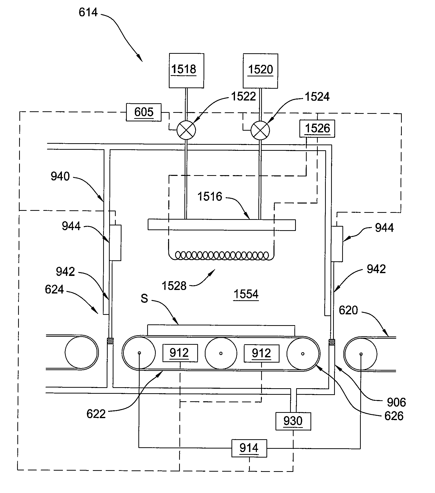
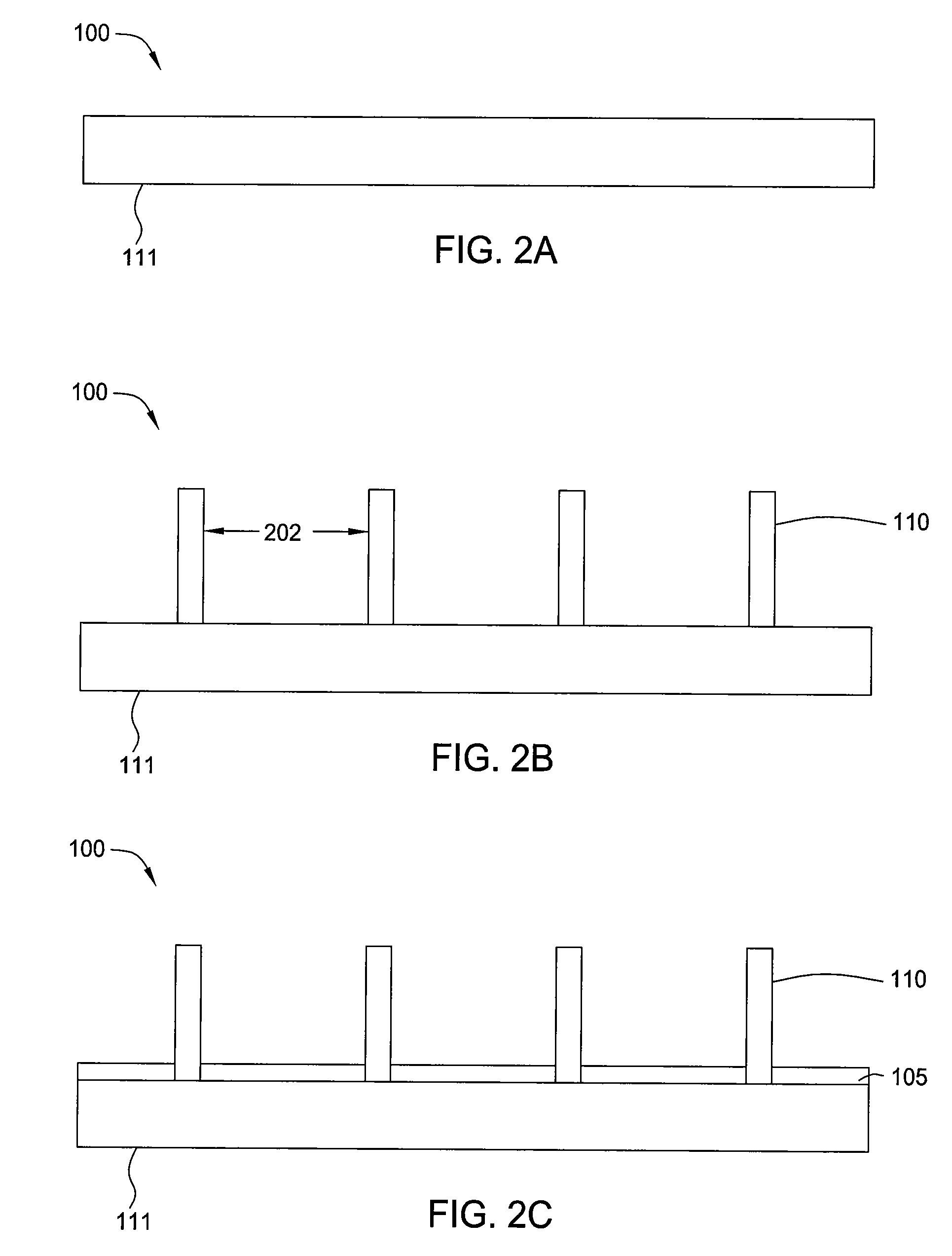
[0007]Embodiments of the present invention generally relate to the formation of an energy storage device. More particularly, embodiments described herein relate to an apparatus and methods used to form electric batteries and electrochemical capacitors. In one embodiment a method of producing an energy storage device is provided. The method comprises positioning an anodic current collector into a processing region, depositing one or more three-dimensional electrodes separated by a finite distance on a surface of the anodic current collector such that portions of the surface of the anodic current collector remain exposed, depositing a conformal polymeric layer over the anodic current collector and the one or more three-dimensional electrodes using iCVD techniques comprising flowing a gaseous monomer into the processing region, flowing a gaseous initiator into the processing region through a heated filament to form a reactive gas mixture of the gaseous monomer and the gaseous initiator, wherein the heated filament is heated to a temperature between about 300° C. and about 600° C., depositing a conformal layer of cathodic material over the conformal polymeric layer, and depositing a cathodic current collector over the conformal layer of cathodic material.
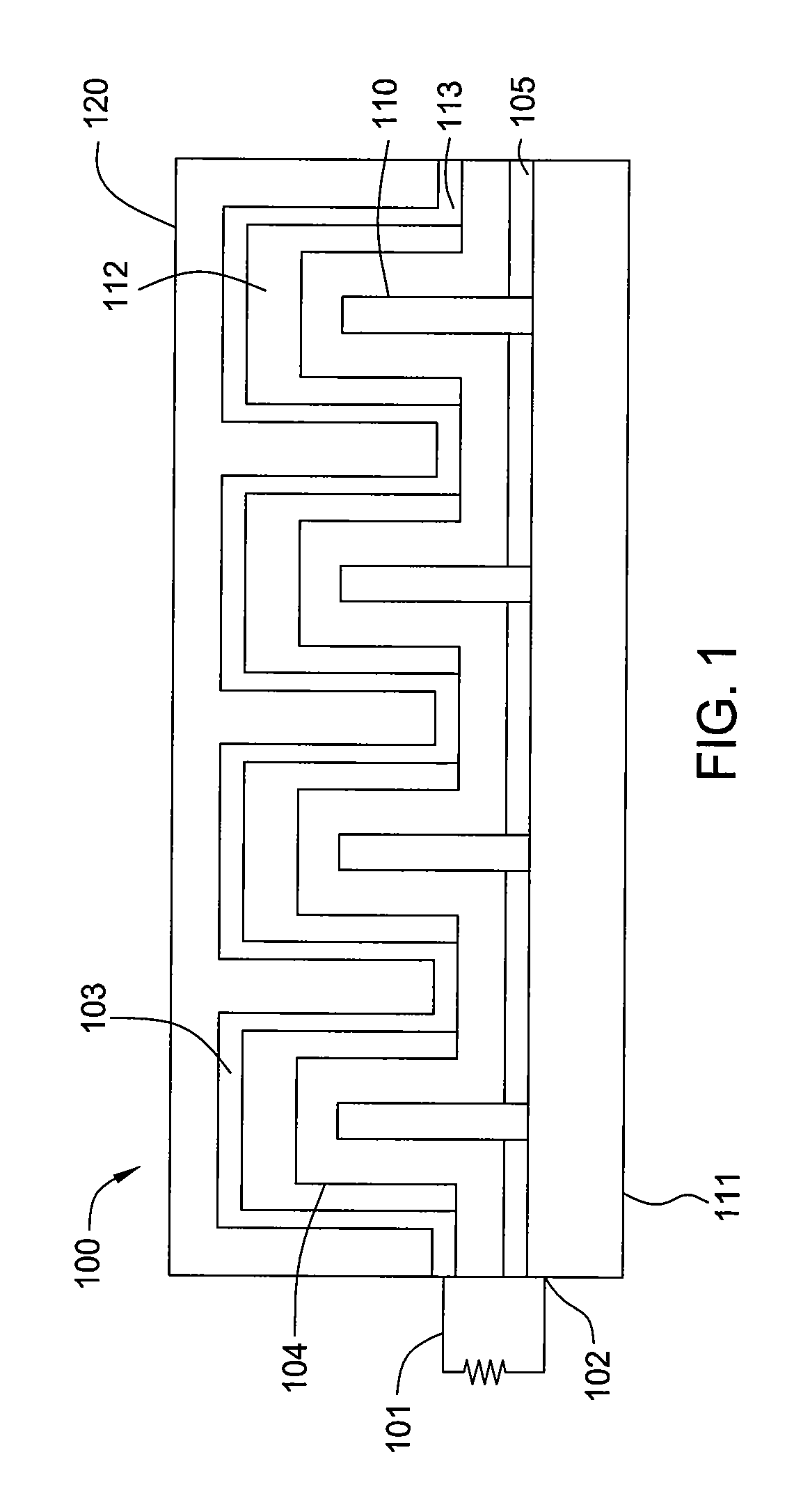
[0008]In another embodiment, an energy storage device is provided. The energy storage device comprises an anodic current collector substrate, one or more three-dimensional anode electrodes separated by a finite distance formed on a surface of the anodic current collector substrate such that portions of the surface of the anodic current collector remain exposed, an insulator layer disposed on the exposed portions of the surface of the anodic current collector between the one or more three-dimensional electrodes, a conformal electrolytic polymeric layer formed over the on

Problems solved by technology

In addition, the size, weight, and / or expense of such energy storage devices can be significant limitations.
Further, low internal resistance is necessary for high performance.
In the case of a battery, internal resistance in a battery impacts performance by reducing the total amount of useful energy stored by the battery as well as the ability of the battery to deliver the high current pulses demanded by digital devices.

Method used


Image

  • 3D approach on battery and supercapacitor fabrication by initiation chemical vapor deposition techniques
  • 3D approach on battery and supercapacitor fabrication by initiation chemical vapor deposition techniques
  • 3D approach on battery and supercapacitor fabrication by initiation chemical vapor deposition techniques

Examples


Embodiment Construction

[0027]Embodiments of the present invention provide cost effective methods for the formation of energy storage devices, such as batteries and supercapicitors, using initiation chemical vapor deposition (iCVD) techniques. Certain embodiments described herein include the formation of a conformal electrolytic polymer layer over a carbon nanotube structure using iCVD techniques.

[0028]In one embodiment, aligned nanowires or nanotubes are deposited on a first current collector comprising aluminum, copper, or any other conducting metals. The individual nanowires or nanotubes may be separated by a finite distance which can be varied from 5 nm to 500 nm, while in other embodiments the separation between the bundles of nanowires or nanotubes are from 10 um to 500 um. A thin oxide layer (4 nm to 100 nm) or a non-conducting polymer layer may be deposited to surround either the individual nanowires / nanotubes or the bundles of nanowires / nanotubes. This selective deposition may be carried out using...


PUM

PropertyMeasurementUnit
Temperatureaaaaaaaaaa

Abstract

Methods and apparatus for forming energy storage devices are provided. In one embodiment a method of producing an energy storage device is provided. The method comprises positioning an anodic current collector into a processing region, depositing one or more three-dimensional electrodes separated by a finite distance on a surface of the anodic current collector such that portions of the surface of the anodic current collector remain exposed, depositing a conformal polymeric layer over the anodic current collector and the one or more three-dimensional electrodes using iCVD techniques comprising flowing a gaseous monomer into the processing region, flowing a gaseous initiator into the processing region through a heated filament to form a reactive gas mixture of the gaseous monomer and the gaseous initiator, wherein the heated filament is heated to a temperature between about 300° C. and about 600° C., and depositing a conformal layer of cathodic material over the conformal polymeric layer.

Description

CROSS-REFERENCE TO RELATED APPLICATIONS[0001]This application claims benefit of U.S. provisional patent application Ser. No. 61 / 236,454 (Attorney Docket No. 14006L), filed Aug. 24, 2009, which is herein incorporated by reference in its entirety.BACKGROUND OF THE INVENTION[0002]1. Field of the Invention[0003]Embodiments of the present invention generally relate to the formation of an energy storage device. More particularly, embodiments described herein relate to an apparatus and methods used to form electric batteries and electrochemical capacitors.[0004]2. Description of the Related Art[0005]Fast-charging, high-capacity energy storage devices, such as supercapacitors and lithium (Li+) ion batteries, are used in a growing number of applications, including portable electronics, medical, transportation, grid-connected large energy storage, renewable energy storage, and uninterruptible power supply (UPS) applications. In each of these applications, the charge time and capacity of energ...

Claims


Application Information

Patent Timeline
IPC IPC(8): H01M10/058B05D5/12C23C16/00H01G9/07
CPCH01G9/155H01M10/0565H01M4/1393H01M4/134Y10T29/49115H01M4/1395H01G9/0029Y02E60/13H01M4/661H01M10/0525H01M10/0585H01M4/133Y02E60/122H01G9/0032Y02E60/10Y02P70/50H01G11/36H01G11/86H01G11/84H01G11/26H01G11/10
Inventor PUSHPARAJ, VICTOR L.NARWANKAR, PRAVIN K.NALAMASU, OMKARAM
Owner APPLIED MATERIALS INC
Learn More