Pressure sensor assembly and method of using the assembly

a technology of pressure sensor and assembly, which is applied in the direction of optical radiation measurement, survey, and borehole/well accessories, etc., can solve the problems of significant over-dimension of the sensor housing, optical bend loss in the fiber affecting the measurement, and the temperature grating is susceptible/very sensitive to induced strain

Active Publication Date: 2011-03-03
SHELL USA INC
View PDF11 Cites 57 Cited by
  • Summary
  • Abstract
  • Description
  • Claims
  • Application Information

AI Technical Summary

Problems solved by technology

A shortcoming of the method disclosed in U.S. Pat. No. 6,233,746 is that placement of the temperature grating at close proximity to the pressure grating along the same optical fiber, whereby the temperature FBG is not attached to a supporting mechanism, makes the temperature grating susceptible / very sensitive to induced strain caused by the movements of the diaphragm and / or vibration or shock of the sensor housing.
Using the sensing system as disclosed in U.S. Pat. No. 6,233,746, and in international patent applications WO2006097772 and WO2007003445 with the improved temperature-compensating scheme based on nominally identical wavelengths requires extra fiber which must be coiled inside the sensor housing, which may cause optical bend-losses in the fiber affecting the measurement, and / or a significant over-dimension of the sensor housing to an extent that it may become too large to fit downhole in a well.

Method used


Image

  • Pressure sensor assembly and method of using the assembly
  • Pressure sensor assembly and method of using the assembly
  • Pressure sensor assembly and method of using the assembly

Examples


Embodiment Construction

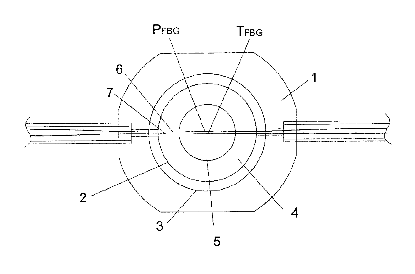
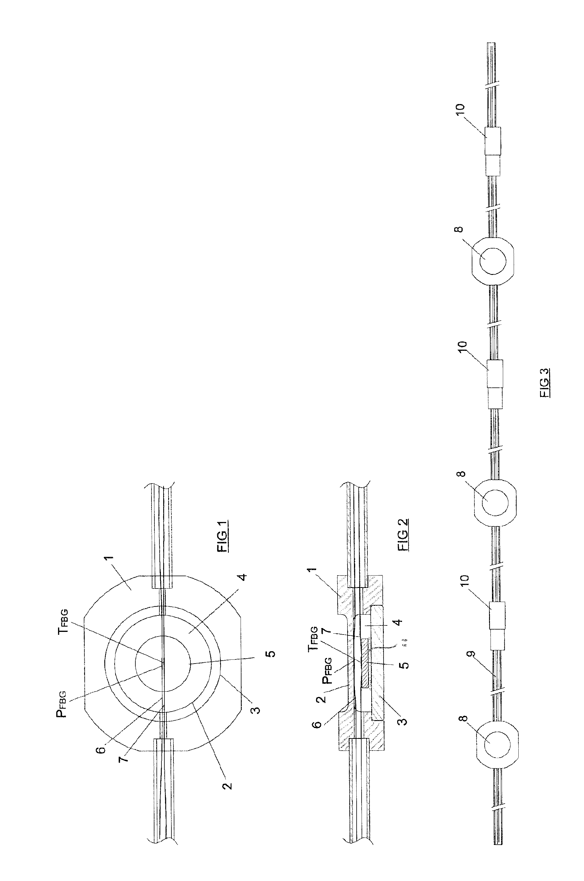
[0044]FIGS. 1 and 2 depict a fiber optic sensor assembly according to the invention comprising a housing 1, which is also referred to as the pressure cell 1. The upper wall of the housing 1 defines a diaphragm 2. The housing comprises a bottom cap 3, which is sealed and secured in a recess at the bottom of the housing 1 and in the interior 4 of the housing a coupon 5 is arranged, by a flexible filler 11, such as a gel or silicone composition which defines a strain-decoupled connection mechanism 11.

[0045]The geometry of the sensor diaphragm 2 is defined as a thick plate membrane, with a flat surface on both sides, having an aspect ratio a / b close to 1, where a and b are the inside length and width of the diaphragm.

[0046]The diaphragm 2 is responsive to an external force such as pressure and also temperature, while the strain-decoupled coupon 5 is responsive only to temperature by way of thermal expansion, not affected by an external force or pressure.

[0047]The diaphragm 2 and the str...


PUM

PropertyMeasurementUnit
aspect ratioaaaaaaaaaa
lengthaaaaaaaaaa
aspect ratio aaaaaaaaaaa

Abstract

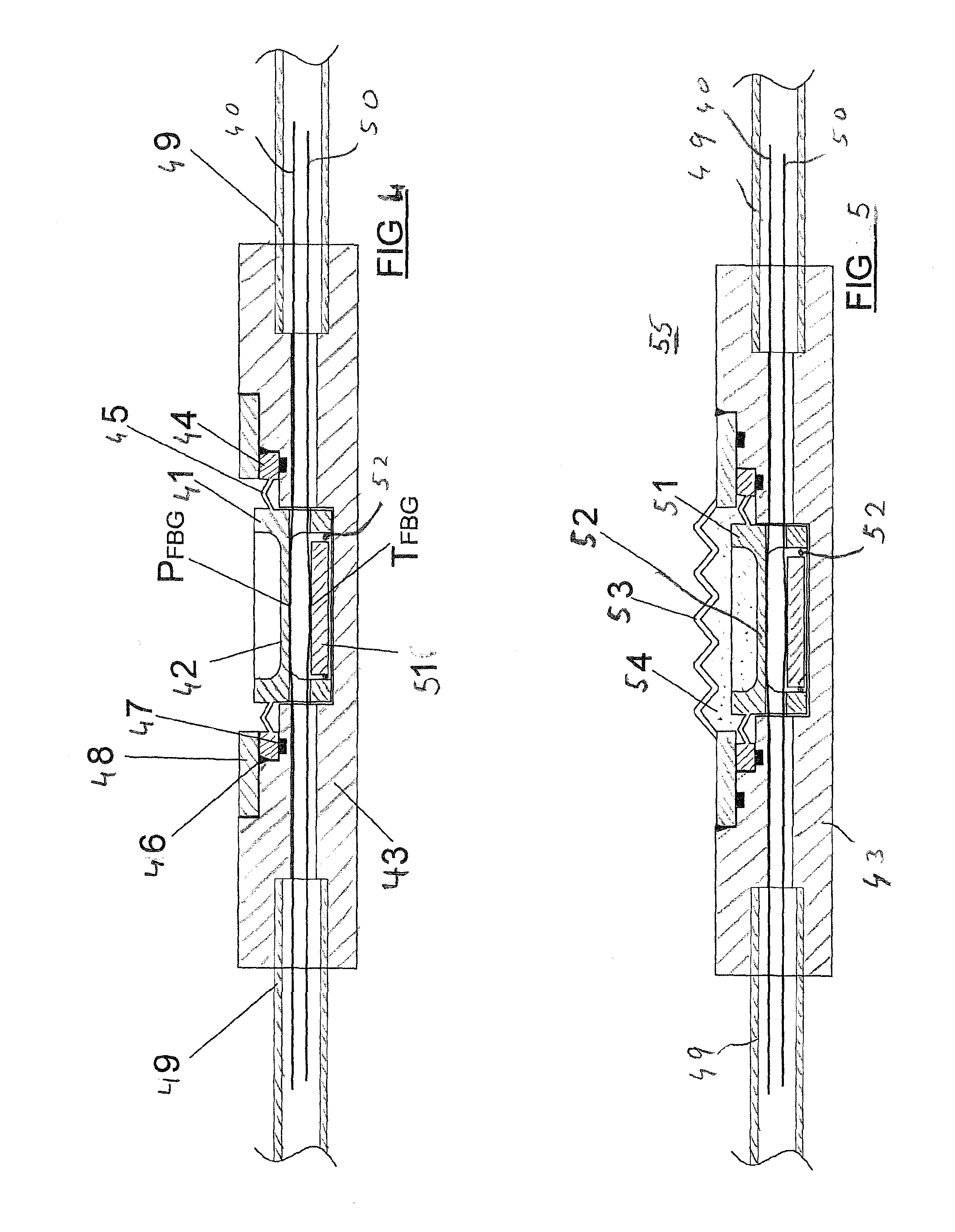
A pressure sensor assembly comprises a sensor housing having a flexible wall that is configured to deform in response to a pressure difference between the interior and exterior of the sensor housing; —a first fiber optical cable section that is bonded to the flexible wall of the sensor housing such that the length of the first fiber optical cable section changes in response to deformation of the wall in response to the said pressure difference; a second fiber optical cable section which is bonded to a thermal reference body, which body is connected to the sensor housing by a strain decoupled connection mechanism, such as a tack weld or flexible glue, and is configured to deform substantially solely in response to thermal deformation, such that the length of the second fiber optical cable section solely changes in response to thermal deformation of the thermal reference body.

Description

BACKGROUND OF THE INVENTION[0001]The present invention relates to a pressure sensor assembly and to a method of using the assembly.[0002]Pressure gauges are widely used in all segments of the industry including exploration and production of hydrocarbons, and in particular for use downhole in oil and gas wells. Pressure gauges are typically constructed using piezoelectric, ferroelectric and resonant quartz components that are active to pressure and temperature characteristics.[0003]Fiber optic pressure gauges have become available over the last decade.[0004]Fiber optic gauges have a number of distinct advantages over electrical gauges in the sense that fiber optic gauges are refrained from on-board electronics, unaffected by electromagnetic interference and inherently intrinsically safe. As such, fiber optic gauges are often used in explosive or flammable environments, and for use at high ambient temperatures, like in oil and gas wells.[0005]U.S. Pat. No. 6,233,746 discloses a soluti...

Claims


Application Information

Patent Timeline
Patent Type & Authority Applications(United States)
IPC IPC(8): G01L11/02G01L9/04G01J3/44
CPCE21B47/06G01L11/025G01L9/0076
Inventor BIRCH, WILLIAMDEN BOER, JOHANNIS JOSEPHUSDOYLE, CRISPIN THOMAS MATTHEWFRANZEN, ANDREJAASKELAINEN, KARI-MIKKOSTAVELEY, CHRISTOPHER BARRY
Owner SHELL USA INC
Why Eureka
Try Eureka