Air conditioner for vehicle

a technology for air conditioners and vehicles, applied in vehicle components, vehicle heating/cooling devices, railway heating/cooling, etc., to achieve the effect of restricting the deterioration of the fuel consumption of the vehicl

Inactive Publication Date: 2011-03-03
DENSO CORP
View PDF7 Cites 51 Cited by
  • Summary
  • Abstract
  • Description
  • Claims
  • Application Information

AI Technical Summary

Benefits of technology

[0011]In view of the foregoing problems, it is an object of the present invention to provide an air conditioner for a vehicle, which can suitably perform heating of a vehicle compartment while restricting deterioration of a fuel consumption of the vehicle, even when exhaust heat of a vehicle equipment used as a heating source in a heating of the vehicle compartment is insufficient for suitably performing the heating.
[0013]Thus, even when the temperature of the thermal fluid is insufficient for suitably performing the heating of the vehicle compartment, the temperature of air to be blown into the vehicle compartment can be increased by using the heating capacity of the second heater, thereby suitably performing the heating of the vehicle compartment. Furthermore, it can prevent the temperature of the vehicle equipment itself from being excessively lower than the predetermined temperature T1.
[0014]Accordingly, even when the exhaust heat of the vehicle equipment is insufficient for performing the heating of the vehicle compartment, it can prevent the vehicle equipment from being unnecessary operated due to the heating of the vehicle compartment, thereby preventing the fuel consumption from being deteriorated. As a result, it is possible to suitably perform heating of the vehicle compartment while restricting deterioration of the fuel consumption of the vehicle, even when exhaust heat of the vehicle equipment used as the heating source in the heating of the vehicle compartment is insufficient for suitably performing the heating.
[0016]Thus, even when the temperature of the thermal fluid is insufficient to perform the heating of the vehicle compartment, the temperature of air to be blown into the vehicle compartment can be sufficiently increased to the desired temperature by using the heating capacity of the second heater. Therefore, the heating of the vehicle compartment can be suitably performed.
[0017]Furthermore, even when the exhaust heat of the vehicle equipment is insufficient for performing the heating of the vehicle compartment, it can prevent the vehicle equipment from being unnecessary operated due to the heating of the vehicle compartment, thereby preventing the fuel consumption from being deteriorated. As a result, it is possible to suitably perform heating of the vehicle compartment while restricting deterioration of a fuel consumption of the vehicle, even when exhaust heat of a vehicle equipment used as a heating source in the heating of the vehicle compartment is insufficient for suitably performing the heating.
[0026]In the air conditioner according to any one of the first and second aspects of the present invention, the second heating capacity control means may increase the heating capacity of the second heater before the first heating capacity control means reduces the heating capacity of the first heater.

Problems solved by technology

As a result, it is possible to suitably perform heating of the vehicle compartment while restricting deterioration of the fuel consumption of the vehicle, even when exhaust heat of the vehicle equipment used as the heating source in the heating of the vehicle compartment is insufficient for suitably performing the heating.

Method used


Image

  • Air conditioner for vehicle
  • Air conditioner for vehicle
  • Air conditioner for vehicle

Examples


first embodiment

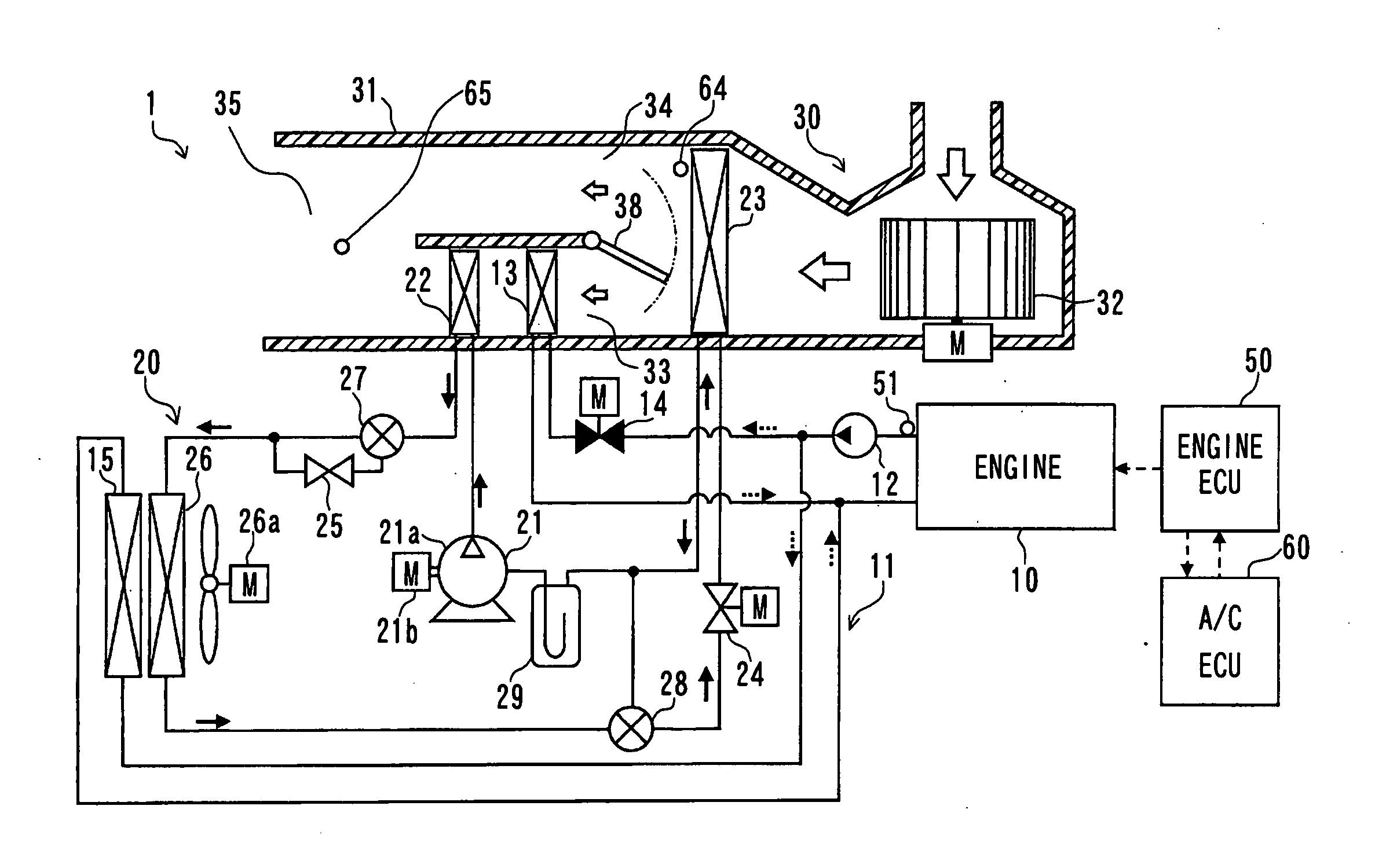
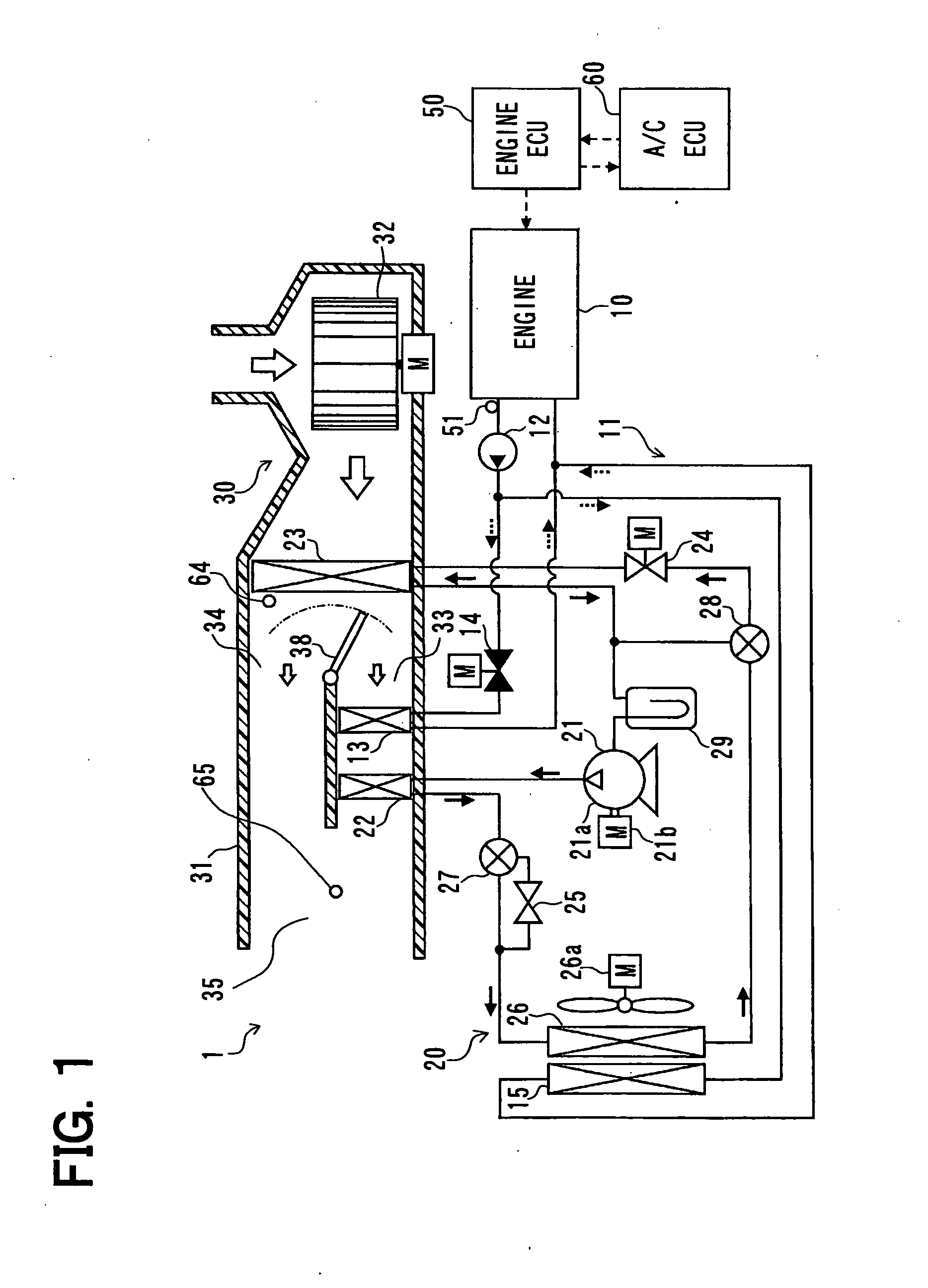
[0046]A first embodiment of the invention will be described below with reference to FIGS. 1 to 8. FIG. 1 is a schematic diagram showing an air conditioner 1 for a vehicle according to a first embodiment of the invention. In the present embodiment, the air conditioner 1 is typically used for a hybrid vehicle which is traveled by a vehicle driving force composed of an internal combustion engine 10 and an electrical motor for a vehicle traveling.

[0047]In the hybrid vehicle of the embodiment, the engine 10 is operated or stopped in accordance with a traveling load of the vehicle. Thus, the hybrid vehicle can be switched to a traveling state in which the vehicle is traveled by using driving force from both of the engine 10 and the electrical motor for traveling, or a traveling state (i.e., EV traveling state) in which the vehicle is traveled only by using the electrical motor for traveling while the engine is stopped. Thus, in the hybrid vehicle, fuel consumption can be improved as compa...

second embodiment

[0165]A second embodiment of the invention will be described with reference to FIGS. 5 and 10.

[0166]In the above-described first embodiment, the flow adjustment valve 14 is used as an example of the heating capacity changing portion. However, in the second embodiment, the flow adjustment valve 14 is omitted, and a bypass passage 16 and an open degree adjustment valve 17 are used as the heating capacity changing portion. The bypass passage 16 is configured such that the coolant flows through the bypass passage 16 while bypassing the heater core 13. Furthermore, the open degree adjustment valve 17 is configured to adjust an open degree of the bypass passage 16 so as to change the flow amount of the engine coolant flowing through the heater core 13.

[0167]Furthermore, in the present embodiment, at step S11 of FIG. 5, the flow amount Gw of the coolant is determined such that the heating capacity of the heater core 13 is approached to the allowable heating capacity Qw_cap, and the open de...

third embodiment

[0169]A third embodiment of the invention will be described with reference to FIGS. 5 and 11.

[0170]In the above-described first and second embodiments, the heating capacity changing portion is configured to change the flow amount of engine coolant flowing through the heater core 13. However, in the present embodiment, as shown in FIG. 11, the flow amount of air flowing through the heater core 13 is changed so that the heating capacity of the heater core 13 is changed.

[0171]Because the allowable heating capacity Qw_cap is an allowable heat radiation amount of the heater core 13, the allowable heat radiation amount of the heater core 13 is the maximum heat absorbing amount of air in the heater core 13. Thus, by changing the maximum heat absorbing amount of air, the heat radiation amount of the heater core 13, that is, the heating capacity of the heater core 13 can be changed.

[0172]In the present embodiment, a heater-core bypass passage 36 is provided in the first air passage 33, so th...


PUM


Abstract

In an air conditioner for a vehicle with an equipment controlled in accordance with a traveling state of the vehicle, a first heater is disposed to heat air to be blown into a vehicle compartment by using a coolant of the equipment as a heat source, and a second heater is adapted as an auxiliary heater to further heat the air heated by the first heater. A heating capacity of the first heater is controlled such that a temperature of the equipment is approached to a predetermined temperature when the thermal fluid after passing through the first heater returns the equipment, and a heating capacity of the second heater is controlled such that a temperature of air to be blown into the vehicle compartment becomes a desired temperature.

Description

CROSS REFERENCE TO RELATED APPLICATION[0001]This application is based on Japanese Patent Applications No. 2009-203433 filed on Sep. 3, 2009, and No. 2010-161416 filed on Jul. 16, 2010, the contents of which are incorporated herein by reference in its entirety.FIELD OF THE INVENTION[0002]The present invention relates to an air conditioner for a vehicle, which can perform a heating of a vehicle compartment by using an exhaust heat of an equipment mounted to the vehicle, operated in accordance with a traveling state of the vehicle.BACKGROUND OF THE INVENTION[0003]Conventionally, Patent Document 1 (JP-2001-1749A corresponding to US 2003 / 0182955A1) describes regarding a vehicle air conditioner, which performs a heating of a vehicle compartment by heating air to be blown into the vehicle compartment by using both an interior heat exchanger of a heat pump cycle and a heater core. Here, the interior heat exchanger is operated as a condenser for cooling and condensing refrigerant in the heat...

Claims


Application Information

Patent Timeline
Patent Type & Authority Applications(United States)
IPC IPC(8): B60H1/02B60H1/32
CPCB60H1/00885B60H1/3213B60H1/00921
Inventor NISHIKAWA, MICHIOKAKEHASHI, NOBUHARU
Owner DENSO CORP
Why Eureka
Try Eureka