Architecture for gas cooled parallel microchannel array cooler

a technology of parallel microchannel arrays and coolers, applied in the field of microchannel heat sink cooling systems, can solve the problems of complex design considerations, high design challenges of cooling components such as components, and achieve the effects of minimal pressure drop, maximum core performance, and low cos

Active Publication Date: 2011-03-03
RAYTHEON CO
View PDF10 Cites 6 Cited by
  • Summary
  • Abstract
  • Description
  • Claims
  • Application Information

AI Technical Summary

Benefits of technology

[0009]Embodiments of the present invention reduce or overcome these problems using a separate manifold structure to deliver cool air and exhaust warm air, combined with a microchannel array cooler that uses micro-plenums (spreading cavities) integrated into the microchannel core, which allows segregated circular or slot nozzle delivered airflow jets to distribute into the microchannel core to achieve maximum core performance. This allows a compact design to reject a large amount of heat with minimal pressure drop. In addition, the separate manifold is isolated from direct contact with the cooler, leading to a lower flow resistance design that requires less air mover power without a reduction in thermal performance.
[0010]Designing the cool air delivery passages (or channels) in the manifold in a complementary sawtooth pattern with the warm air exhaust passages improves both cool air delivery through nozzles in the manifold and warm air exhaustion through openings in the manifold. Power consumption can be kept low by using an array of small fans to provide the airflow. Such a system is capable of rejecting a large amount of heat in a small amount of space using minimal air mover electrical power. In addition, the system is capable of using ambient air as the coolant. Also, the manifold and cooler can be made of durable components that do not need to maintain physical contact, thus greatly reducing the risk of damage from shock or vibration.

Problems solved by technology

Cooling such components can present many design challenges.
Environmental factors can further complicate design considerations.
Jet impingement cooling, on the other hand, uses narrow high-speed jets of coolant directed at the heat source, causing rapid cooling, limited primarily to the region receiving the direct impact of the jets.
Microchannel heat sinks can suffer from insufficient coolant pressure to dissipate the heat from the large surface area while jet impingement cooling can suffer from the somewhat localized area of heat rejection.
Effective air cooled microchannel arrays with parallel flow on a micro electro mechanical systems (MEMS) scale, however, is prohibited by unfavorable flow patterns in simple rectangular arrays of fins.
The primary problem encountered is the inability of the flow stream to penetrate a sufficient depth into the fin core to achieve the desired fin efficiency.
In addition, the separate manifold is isolated from direct contact with the cooler, leading to a lower flow resistance design that requires less air mover power without a reduction in thermal performance.

Method used


Image

  • Architecture for gas cooled parallel microchannel array cooler
  • Architecture for gas cooled parallel microchannel array cooler
  • Architecture for gas cooled parallel microchannel array cooler

Examples


Embodiment Construction

[0048]Exemplary embodiments of the present invention will now be described in more detail with reference to the accompanying drawings. In the drawings, like reference numerals refer to like elements throughout.

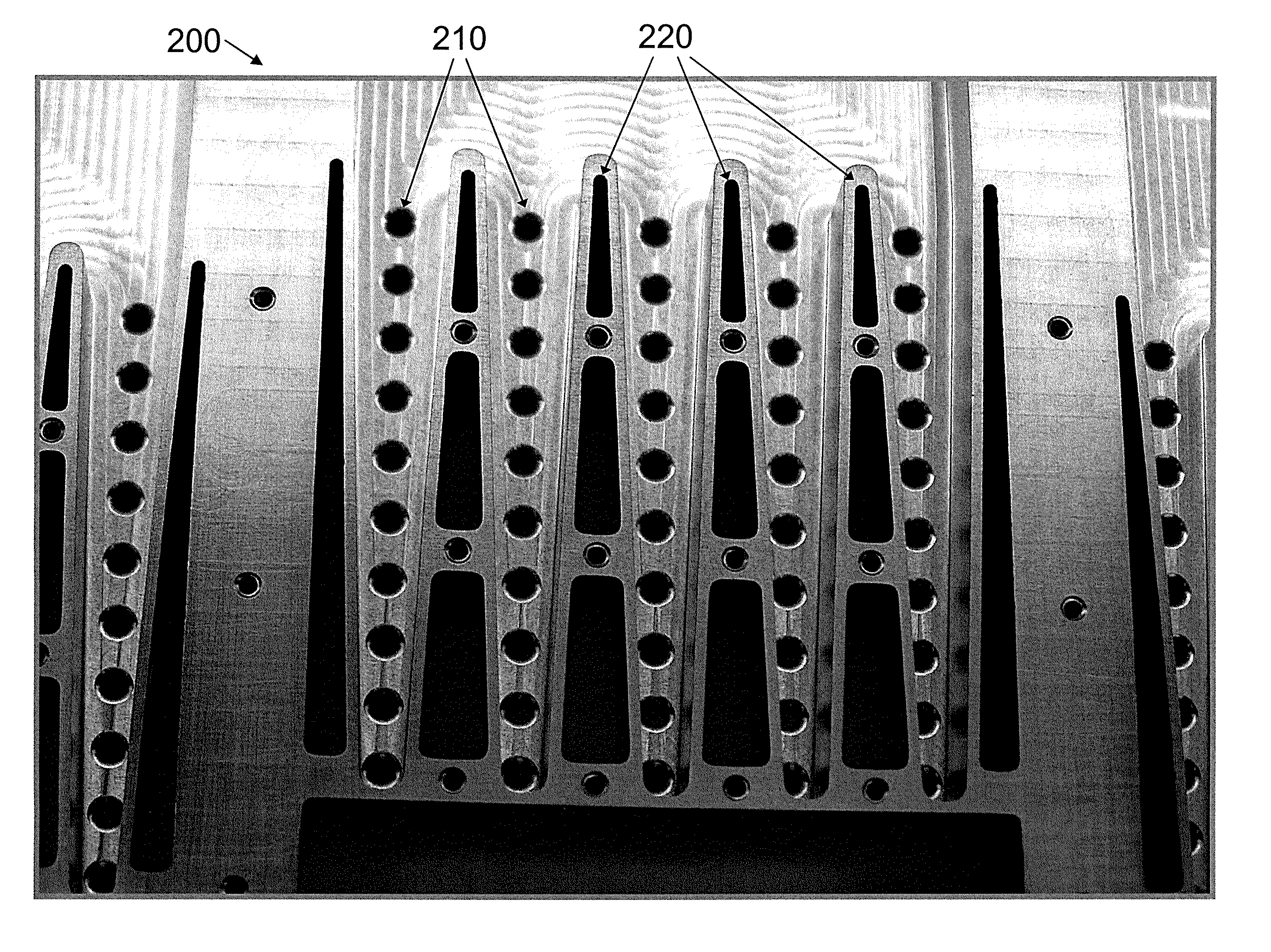
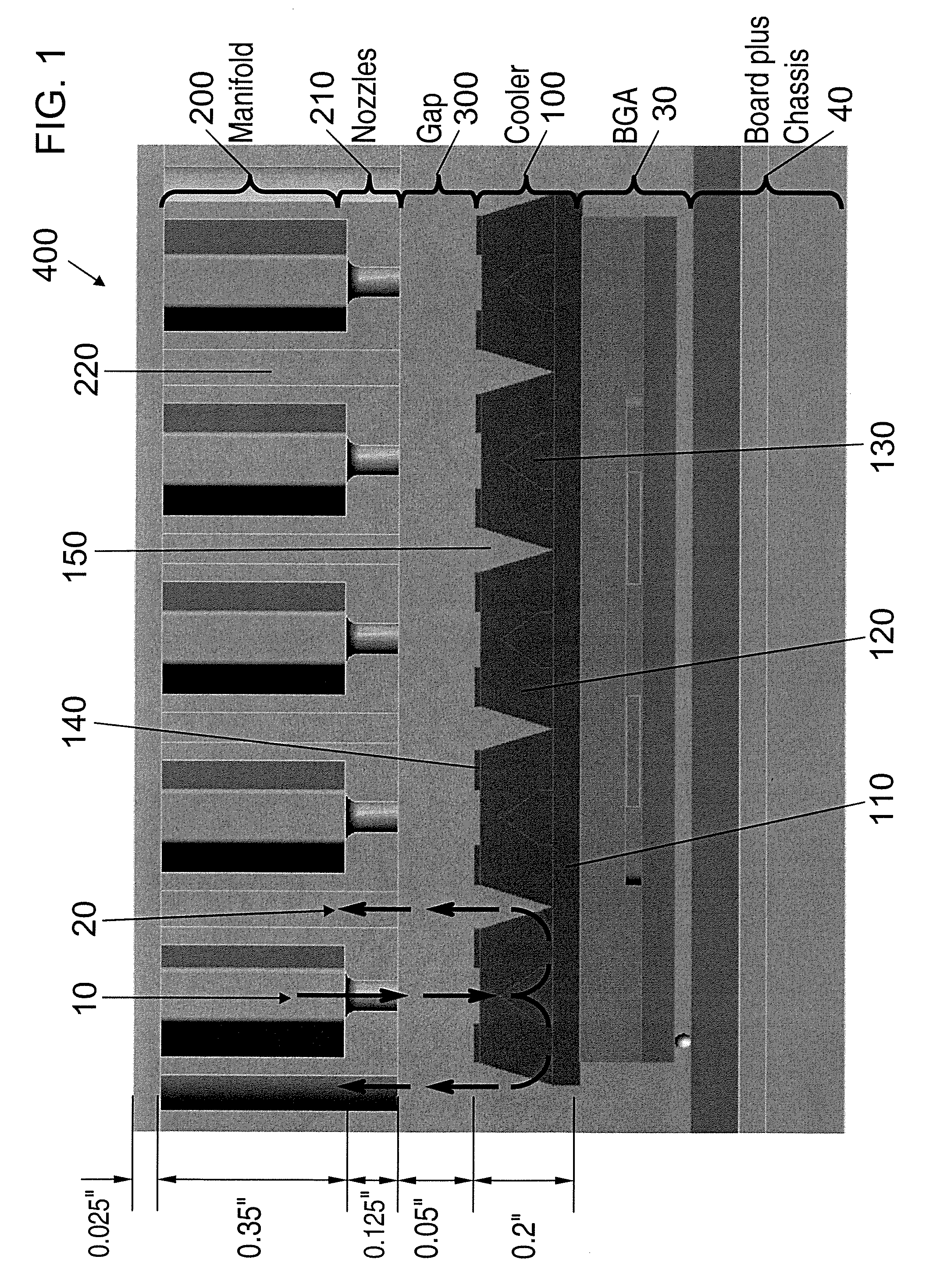
[0049]Referring now to FIG. 1, in a side view (i.e., a widthwise view) of an exemplary embodiment of the present invention, an air-cooled parallel microchannel array cooling device 400 is shown attached to an example heat source, in this case a ball grid array (BGA) 30 mounted on a circuit board with chassis 40. The heat source can be anything, electronics or otherwise. While this particular cooling device uses air with which to cool, the present invention is not limited thereto. For instance, any gas may serve as a cooling medium. For purposes of this disclosure, therefore, air will serve as an example cooling gas.

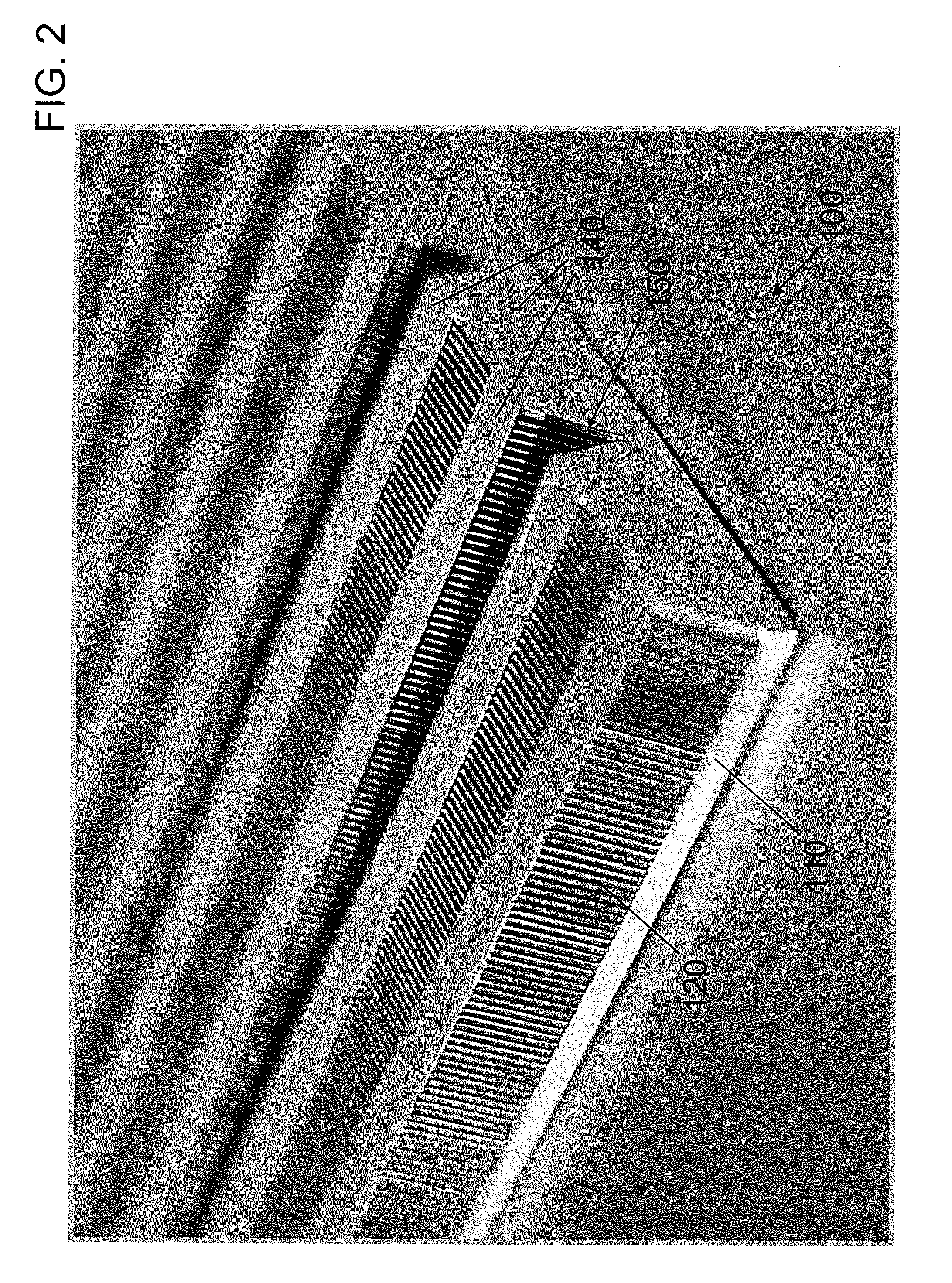
[0050]The cooling device 400 includes a parallel microchannel array cooler 100 and a manifold 200. The cooler 100 includes a base 110 attached to the heat source (i...


PUM


Abstract

Effective utilization of a parallel flow air-cooled microchannel array at the micro electro mechanical systems (MEMS) scale is prohibited by unfavorable flow patterns in simple rectangular arrays. The primary problem encountered is the inability of the flow stream to penetrate a sufficient depth into the fin core to achieve the desired fin efficiency. Embodiments of the present invention overcome this problem using a manifold with open nozzle discharge and integrated lateral exhaust along with a microchannel array cooler with micro spreading cavities for internal air distribution.

Description

CROSS-REFERENCE TO RELATED APPLICATION(S)[0001]This application claims priority to and the benefit of U.S. Provisional Patent Application No. 61 / 238,096, entitled “Architecture for Gas Cooled Parallel Microchannel Array Cooler,” filed on Aug. 28, 2009 in the U.S. Patent and Trademark Office, the entire content of which is herein incorporated by reference.BACKGROUND[0002]1. Field[0003]Aspects of embodiments of the present invention relate to cooling systems. More specifically, aspects of embodiments of the present invention relate to microchannel heat sink cooling systems.[0004]2. Description of Related Art[0005]Modern electronics, such as computer processor chips, are capable of generating enormous amounts of heat in a small amount of space. Cooling such components can present many design challenges. Environmental factors can further complicate design considerations. For instance, on military aircraft, where the size, weight, power consumption, and durability of any hardware (such a...

Claims


Application Information

Patent Timeline
Patent Type & Authority Applications(United States)
IPC IPC(8): F28F9/02
CPCH01L23/4336H01L23/467H01L2924/0002H01L2924/00H05K7/20136H01L23/46
Inventor JOHNSON, SCOTT T.
Owner RAYTHEON CO
Why Eureka
Try Eureka