Substrate holder, substrate supporting apparatus, substrate processing apparatus, and substrate processing method using the same

Inactive Publication Date: 2011-03-03
CHARM ENG CO LTD
View PDF5 Cites 334 Cited by
  • Summary
  • Abstract
  • Description
  • Claims
  • Application Information

AI Technical Summary

Benefits of technology

[0018]According to the teaching of the present disclosure, plasma can be uniformly generated at the back surface of a substrate to improve the etch uniformity across the back surface of the substrate. In detail, leakage of reaction gas injected toward a substrate placed in the chamber is prevented by using the substrate holder having variously shaped and sized exhaust holes at its sidewall, so that plasma generated between the substrate and the electrode can be stayed for a constant time, and reaction gas can flow smoothly for uniform distribution across the back surface of the substrate.
[0019]Furthermore, the substrate holder may have a divided structure, and in this case, the substrate holder can be partially re-machined or replaced without having to re-machine or replace the substrate holder wholly when the substrate holder is broken. Therefore, maintenance machining can be easily performed, and maintenance costs can be reduced.
[0020]Furthermore, the substrate s

Problems solved by technology

Particularly, since such thin layer deposition and etch processes are performed on the same surface (front surface) of a substrate, foreign substances such as thin layers and particles deposited on the back surface of the substrate during the thin layer deposition process are not removed, and the remaining foreign substances cause various problems such as bending and misalignment of the substrate in a subsequent process.
However, since such a conventional substrate supporting apparatus has an opened side not to interfere with a carrying unit used to carry a substrate into a chamber, reaction gas injected to the back surface of a substrate supported by the substrate supporting apparatus may leak or split due to the opened side of the substrate supporting apparatus.
This reduces the etch uniformity of the back surface of the substrate.
Therefore, the structure of the substrate supporting apparatus is complex and it is difficult to use the inside space of the chamber.
In addition, since the driving units are individually controlled for actuating the substrate holder and the lower electrode, the pro

Method used


Image

  • Substrate holder, substrate supporting apparatus, substrate processing apparatus, and substrate processing method using the same
  • Substrate holder, substrate supporting apparatus, substrate processing apparatus, and substrate processing method using the same
  • Substrate holder, substrate supporting apparatus, substrate processing apparatus, and substrate processing method using the same

Examples


Embodiment Construction

[0048]Hereinafter, specific embodiments will be described in detail with reference to the accompanying drawings. The present invention may, however, be embodied in different forms and should not be construed as limited to the embodiments set forth herein. Rather, these embodiments are provided so that this disclosure will be thorough and complete, and will fully convey the scope of the present invention to those skilled in the art. In the figures, like reference numerals refer to like elements throughout.

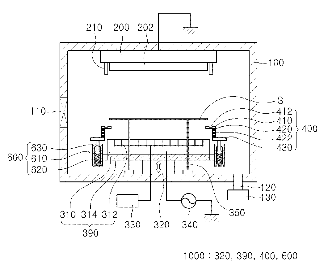
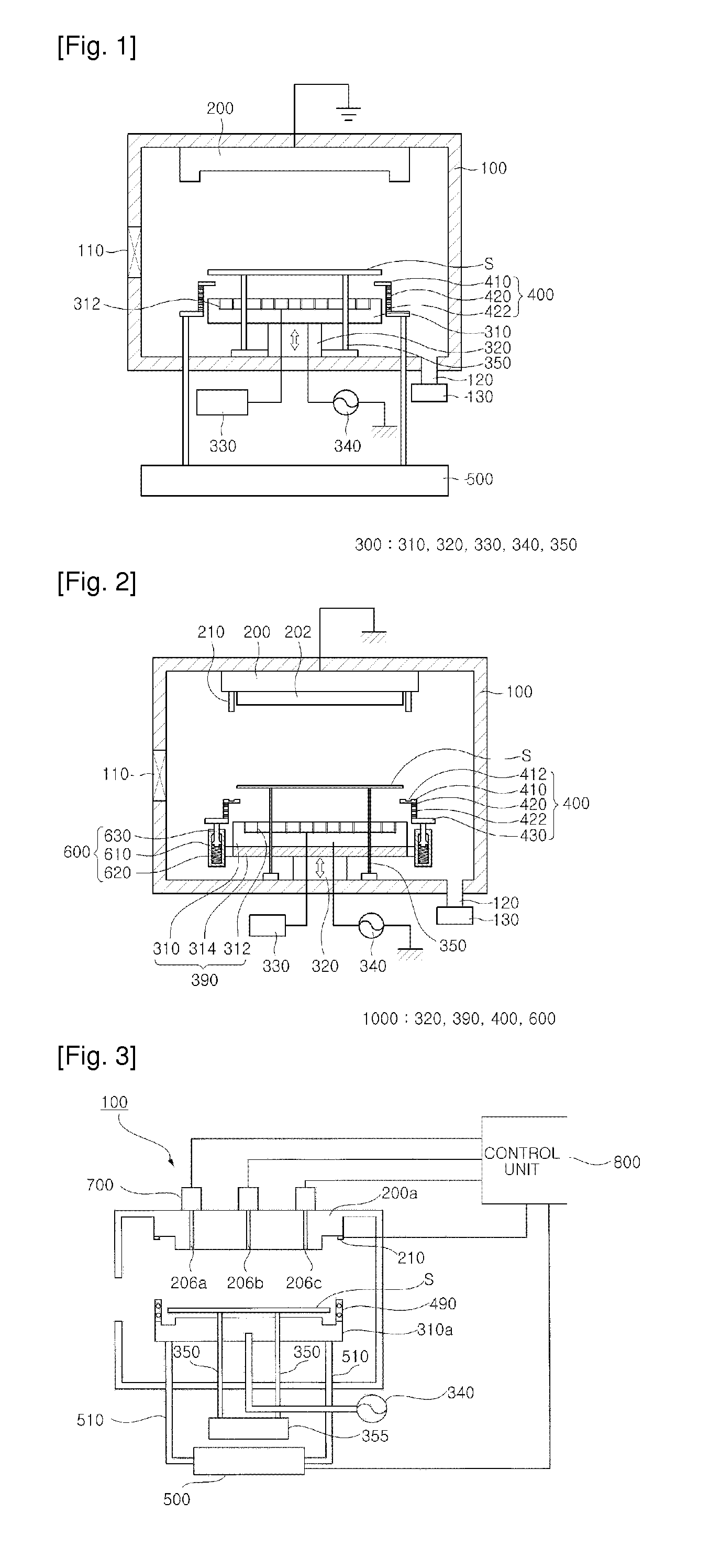
[0049]FIG. 1 is a cross-sectional view illustrating a substrate processing apparatus in accordance with an exemplary embodiment, and FIG. 2 is a cross-sectional view illustrating a substrate processing apparatus in accordance with another exemplary embodiment.

[0050]Referring to FIG. 1, the substrate processing apparatus of an embodiment includes a chamber 100, a shield member 200 provided at an upper region of the chamber 100, a gas injection unit 300 disposed at a side opposite to ...


PUM

PropertyMeasurementUnit
Heightaaaaaaaaaa
Circumferenceaaaaaaaaaa
Electric fieldaaaaaaaaaa

Abstract

Provided are a substrate holder, a substrate supporting apparatus, a substrate processing apparatus, and a substrate processing method. Particularly, there are provided a substrate holder, a substrate supporting apparatus, a substrate processing apparatus, and a substrate processing method that are adapted to improve process efficiency and etch uniformity at the back surface of a substrate.

Description

TECHNICAL FIELD[0001]The present disclosure relates to a substrate holder, a substrate supporting apparatus, a substrate processing apparatus, and a substrate processing method, and more particularly, to a substrate holder, a substrate supporting apparatus, a substrate processing apparatus, and a substrate processing method that are adapted to improve process efficiency and etch uniformity at the back surface of a substrate.BACKGROUND ART[0002]Generally, semiconductor apparatuses and flat display apparatuses are manufactured by depositing a plurality of thin layers on the front surface of a substrate and etching the thin layers to form devices having predetermined patterns on the substrate. That is, a thin layer is deposited on the front surface of a substrate by using a deposition apparatus, and then portions of the thin layer are etched into a predetermined pattern by using an etching apparatus.[0003]Particularly, since such thin layer deposition and etch processes are performed o...

Claims


Application Information

Patent Timeline
IPC IPC(8): C23F1/08C23F1/04C23F1/00
CPCH01J37/32623H01J37/32642H01L21/67069H01L21/68721H01J2237/3343H01L21/68785H01J37/3244H01J37/32568H01J37/32715H01L21/68728
Inventor HAN, YOUNG KISEO, YOUNG SOOKIM, HYOUNG WONYOON, CHI KUGLEE, SANG HOON
Owner CHARM ENG CO LTD
Why Eureka
Try Eureka