Driving apparatus for a vehicle-mounted electric motor

a technology of electric motor and driving apparatus, which is applied in the direction of motor/generator/converter stopper, hybrid vehicle, dynamo-electric converter control, etc., can solve the problem that the power supply capacitor cannot be discharged

Inactive Publication Date: 2011-03-03
DENSO CORP
View PDF7 Cites 61 Cited by
  • Summary
  • Abstract
  • Description
  • Claims
  • Application Information

AI Technical Summary

Benefits of technology

[0019]For attaining the first object, a driving apparatus for an electric motor comprises an inverter circuit, a power supply capacitor, a DC power source and a power source switch. The inverter circuit has a plurality of pairs of switching elements connected in parallel between a positive bus and a negative bus. Each pair of the switching elements includes a high-side switching element and a low-side switching element connected in series in correspondence to each phase of the motor. The power supply capacitor is connected between the positive bus and the negative bus. The DC power source is connected between the positive bus and the neutral point of the stator coil. The power source switch is connected between the DC power source and at least one of the positive bus and the neutral point. The inverter circuit is configured to output AC currents to the stator coil based on output voltages of the DC power source and the power supply capacitor by a switching operation of the switching elements. The inverter circuit checks whether the power source switch is in a turned-off state, in which at least one of the positive bus and the neutral point is disconnected from the DC power source. The inverter circuit further controls the switching elements to allow a current to flow from a positive electrode of the power supply capacitor to a negative electrode of the power supply capacitor through the stator coil, when the power source switch is in the turned-off state.
[0020]For attaining the second object, a driving apparatus for an electric motor comprises an inverter circuit, a power supply capacitor, a DC power source and a power source switch. The inverter circuit has a plurality of pairs of switching elements connected in parallel between a positive bus and a negative bus. Each pair of the switching elements includes a high-side switching element and a low-side switching element connected in series in correspondence to each phase of the motor. The power supply capacitor is connected between the neutral point and the negative bus. The DC power source is connected between the positive bus and the neutral point of the stator coil. The power source switch is connected between the DC power source and at least one of the positive bus and the neutral point. The inverter circuit is configured to output AC currents to the stator coil based on output voltages of the DC power source and the power supply capacitor by a switching operation of the switching elements. The inverter circuit checks whether the power source switch is in a turned-off state, in which at least one of the positive bus and the neutral point is disconnected from the DC power source. The inverter circuit further controls the switching elements to allow a current to flow from a positive electrode of the power supply capacitor to a negative electrode of the power supply capacitor through the stator coil, when the power source switch is in th

Problems solved by technology

If the DC power source, the smoothing capacitor and the discharge switch are connected between the positive bus and the neutral point of the stator coil and a power supply capacitor is additionally connect

Method used


Image

  • Driving apparatus for a vehicle-mounted electric motor
  • Driving apparatus for a vehicle-mounted electric motor
  • Driving apparatus for a vehicle-mounted electric motor

Examples


first embodiment

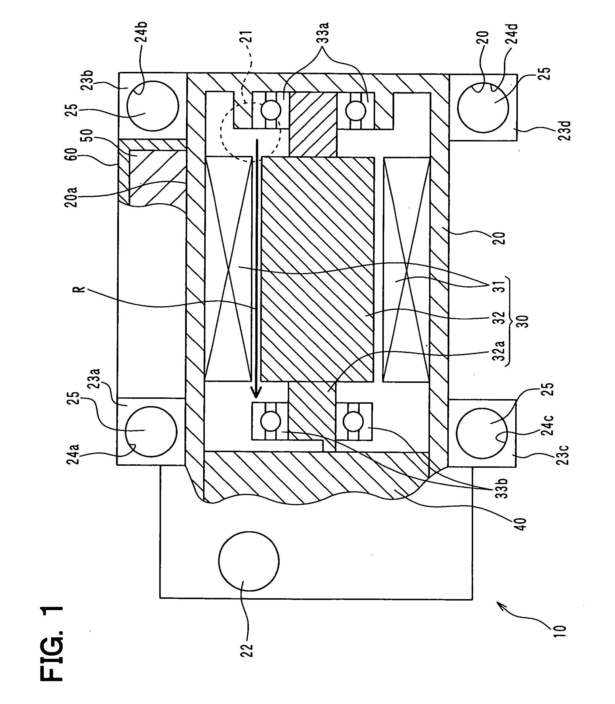
[0053]Referring to FIG. 1, as a driving apparatus for a vehicle-mounted electric motor, an electric compressor device is mounted in an engine compartment of a hybrid vehicle and forms a refrigeration cycle of a vehicular air-conditioning system in combination with a condenser, a pressure reducer and an evaporator. The hybrid vehicle is driven by an internal combustion engine and / or an electric motor.

[0054]The compressor device 10 includes a compressor housing 20, an electric motor 30, a compressor 40, a driving apparatus 50 and a cover 60.

[0055]The housing 20 is made of a metal such as iron or aluminum and formed generally in a cylindrical shape. The housing 20 has a refrigerant inlet port 21, a refrigerant outlet port 22 and attachment feet 23a, 23b, 23c and 23d. The refrigerant inlet port 21 is a passage for suctioning the refrigerant from the evaporator side. The refrigerant outlet port 22 is a passage for discharging the refrigerant toward the condenser.

[0056]The attachment feet...

second embodiment

[0167]According to the second embodiment, the inverter control circuit 72 is configured to gradually decrease the rotation speed of the electric motor 30 before stopping the electric motor 30.

[0168]The second embodiment is different from the first embodiment in the motor rotation speed control processing.

[0169]Specifically, as shown in FIG. 14, this motor rotation speed control processing has steps S90, S100b, S110b, S120b, S130b, S140 and S150 added to the steps shown in FIG. 3. The inverter control circuit 72 executes the motor rotation speed control processing as follows.

[0170]At step S90, it is checked whether the command rotation speed Na outputted from the electronic control unit 90 is higher than a low limit speed Nmin of the rotation speed of the electric motor 30. The low limit speed Nmin is set to be higher than zero but the lowest possible speed, at which the electric motor 30 rotates. If the command rotation speed Na is higher than the low limit speed Nmin (that is, Na>N...

third embodiment

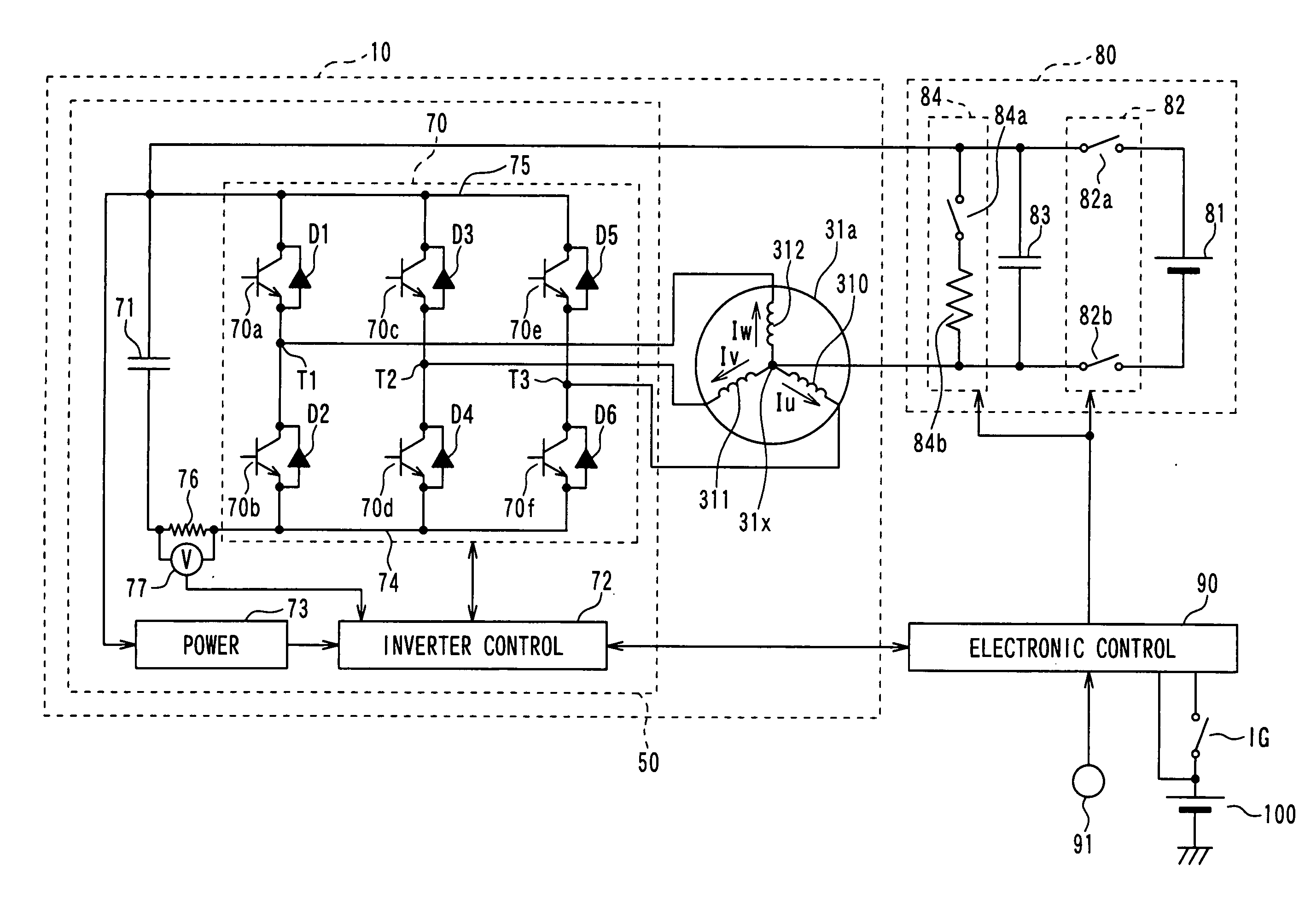
[0198]According to the third embodiment, it is checked whether the system main relay 82 is turned off based on a voltage developed between the positive bus 75 and the neutral point 31x of the stator coil 31a without referring to the main relay-off signal.

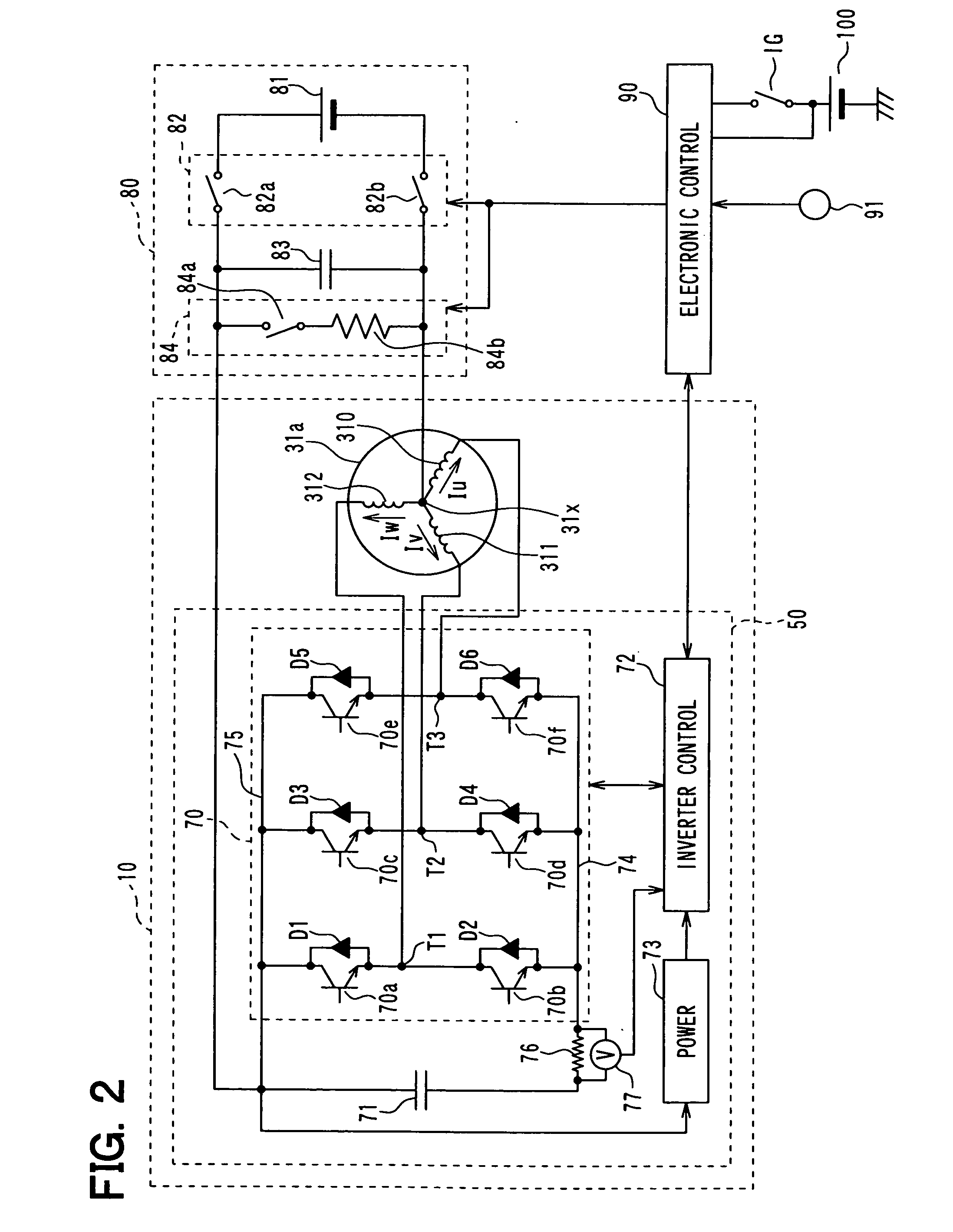
[0199]In the third embodiment, as shown in FIG. 15, the driving apparatus 50 shown in FIG. 2 is further provided with a voltage sensor 91a. The voltage sensor 91a detects the voltage developed between the positive bus 75 and the neutral point 31x of the stator coil 31a. The detection voltage of the voltage sensor 91a is used to check whether the system main relay 82 is turned off by the inverter control circuit 72.

[0200]The inverter control circuit 72 is configured to execute step S200 shown in FIG. 12 in a different manner.

[0201]Specifically, in operation, the electronic control unit 90 turns off the relay switch 84a of the discharge circuit 84 and turns on the switches 82a and 82b of the system main relay 82, when the ignition swi...


PUM


Abstract

An inverter circuit for a motor outputs three-phase AC currents, which are outputted from common connection points to stator coils, based on output voltage of a DC power source and a power supply capacitor by a switching operation of transistors. An inverter control circuit determines that a system main relay is turned off, upon receiving a main relay-off signal from an electronic control unit. The inverter control circuit turns on the low-side transistors, while turning off the high-side transistors. A discharge current flows from the positive electrode to the negative electrode of the power supply capacitor through the stator coil and the low-side transistors, so that electric charge stored in the power supply capacitor is discharged.

Description

CROSS REFERENCE TO RELATED APPLICATION [0001]This application is based on and incorporates herein by reference Japanese patent application No. 2009-199596 filed on Aug. 31, 2009.FIELD OF THE INVENTION[0002]The present invention relates to a driving apparatus for a vehicle-mounted electric motor, which drives an electric motor mounted on a vehicle by electric power of a direct current power source.BACKGROUND OF THE INVENTION[0003]A conventional driving apparatus includes, as disclosed in patent document 1 (JP 2005-73399A), an inverter circuit and a control circuit. The inverter circuit outputs three-phase AC currents to a three-phase AC synchronous motor. The control circuit controls the inverter circuit.[0004]Specifically, the inverter circuit is configured by three sets of a pair of series-connected transistors. The three sets are connected in parallel between a positive bus and a negative bus. A direct current (DC) power source is connected between the positive bus and the negativ...

Claims


Application Information

Patent Timeline
IPC IPC(8): H02P27/00H02M7/48H02M7/5387H02P6/06H02P6/08H02P6/12H02P6/182H02P6/28
CPCB60L3/04B60L11/1811Y02T90/14Y02T90/127Y02T10/7005Y02T10/7072B60L53/20Y02T10/70Y02T90/12
Inventor SUMI, TOMOYUKIAMANO, HIROSHISAKAI, KOJI
Owner DENSO CORP
Why Eureka
Try Eureka