Electromechanical Vampire Proof Battery Charger System

a battery charger and electromechanical technology, applied in the direction of electric vehicles, circuit monitoring/indication, transportation and packaging, etc., can solve the problems of energy conservancy becoming a big issue, dc power supplies incur dynamic and static power loss within the rectification and regulation circuitry, and charger use comes with energy loss, etc., to achieve the effect of reducing manufacturing cost and avoiding vampire power loss

Inactive Publication Date: 2011-03-03
VAMPIRE LABS
View PDF6 Cites 10 Cited by
  • Summary
  • Abstract
  • Description
  • Claims
  • Application Information

AI Technical Summary

Benefits of technology

[0014]Accordingly, it is an object of the present invention to provide a method of eliminating vampire power loss with low manufacturing cost.
[0017]An actual switching mechanism is provided in the form of a conductive short circuit on the phone or other target devices to eliminate vampire energy loss. This actual switching mechanism is capable of being integrated into future target designs.

Problems solved by technology

Nowadays, energy conservancy has become a big issue in the overall global warming concern.
How to prevent vampire energy loss presents a challenge to our industry because vampire energy loss, also called no-load / phantom loads energy loss or standby power loss, constitutes a substantial amount of our nation's energy waste.
However, this charger use comes with energy loss.
According to academic literatures, the cause of no-load loss within transformers is attributed to eddy currents and magnetic hysteresis within the transformer core.
In addition to no-load loss or vampire loss from the transformer, DC power supplies also incur dynamic and static power loss within the rectification and regulation circuitry.
Further, all of these combined losses within the DC power supply attribute to a significant portion of “vampire energy loss” which exists in many electronic product domains.
These conditions may limit the functionality of both the USB Ecostrip and the Smart Power Strip for many peripheral devices which could result in vampire energy loss.
However, this alternative requires more electronic circuitry and is relatively expensive to manufacture.
However, the additional circuitry and solid state devices add more costs and making the solution more expensive to produce.
Furthermore, many inventions lack an application specific shutdown mechanism, which makes the disconnection less elegant where energy loss can occur, such as a smart strip.

Method used


Image

  • Electromechanical Vampire Proof Battery Charger System
  • Electromechanical Vampire Proof Battery Charger System
  • Electromechanical Vampire Proof Battery Charger System

Examples


Embodiment Construction

[0026]The present invention comprises a short circuit feedback loop and requires some hardware support from target devices. The present invention also requires the use of conductive wires and connector plugs to route the AC power source to the target device, then for feedback directly or indirectly to the primary coil of the charger's transformer.

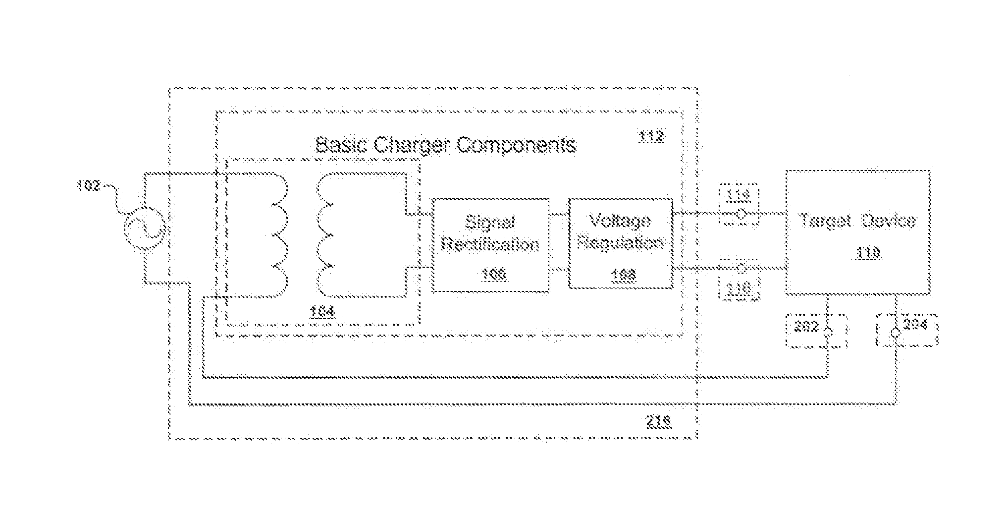
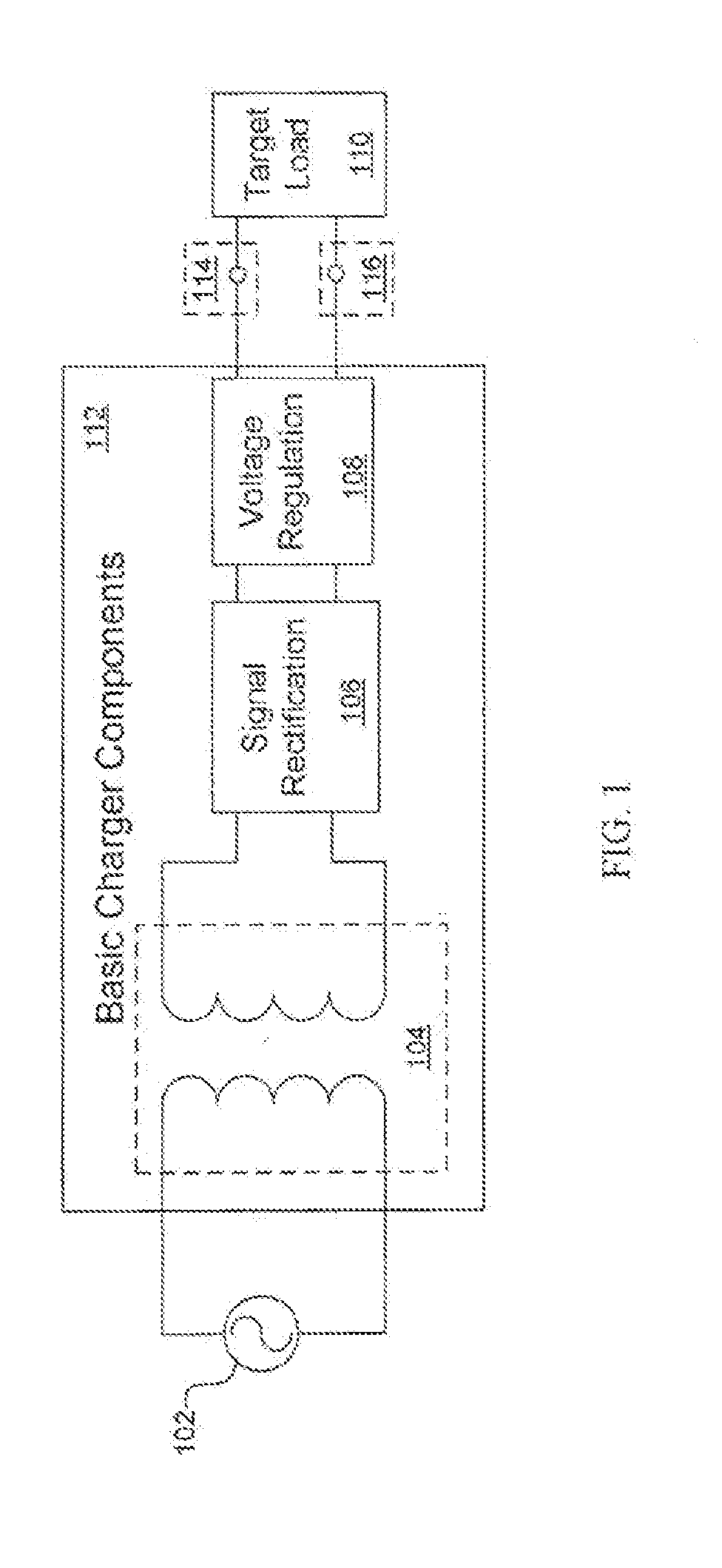
[0027]Now referring to FIG. 2, an AC power source 102, a set of charger components 216, and a target device 110 are depicted. The basic battery charger or DC power supply circuitry 112 is slightly augmented 216 to allow one port of the AC power source 102 to be routed to the target device 110 for feedback directly or indirectly to the primary coil of the step down transformer 104.

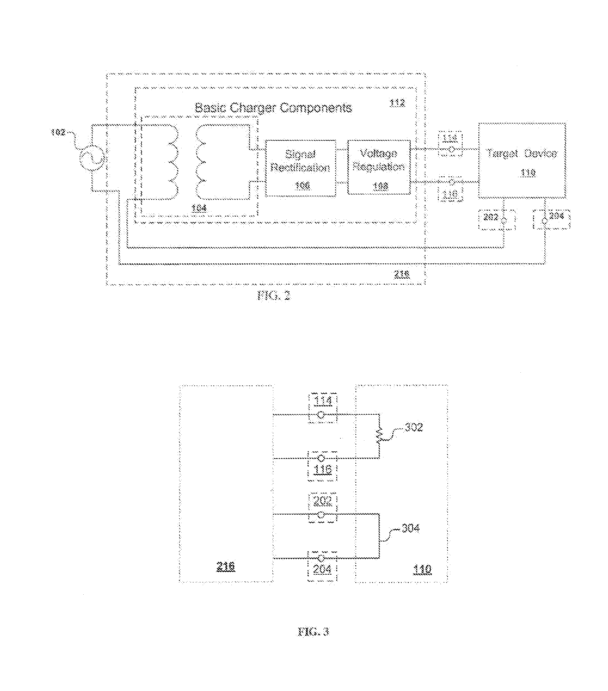
[0028]In this preferred embodiment, a switching mechanism is employed to eliminate vampire energy loss. As shown in FIG. 2, an augmented charger 216 including a charger 112 is connected with a target device 110 in series with an AC power source 102. There are two p...


PUM


Abstract

A method of eliminating vampire energy loss in battery charges is provided. Vampire energy loss occurs when an electronic or mechanical machine consumes energy while not being utilized for the purpose of its existence, for example, energy loss in re-charging consumer electronic devices. By employing the use of an electromechanical switching method that creates a conductive short circuit to the charger after disconnecting the charged target device, the vampire or no load energy loss can be eliminated with or without disconnecting the charger.

Description

[0001]This application claims the benefit of U.S. Provisional Application No. 61 / 154,414, filed on Feb. 22, 2009, which is incorporated herein by reference.FIELD OF INVENTION[0002]The present invention relates to energy loss elimination. Particularly, the present invention relates to power efficient battery chargers and technology that eliminates vampire energy loss by using an electromechanical switching method for the power grid disconnect of the battery charger.BACKGROUND[0003]Nowadays, energy conservancy has become a big issue in the overall global warming concern. How to prevent vampire energy loss presents a challenge to our industry because vampire energy loss, also called no-load / phantom loads energy loss or standby power loss, constitutes a substantial amount of our nation's energy waste.[0004]The basic scheme of a charger with a target load is depicted in FIG. 1. As shown in FIG. 1, the charger is plugged into an AC power source 102 in the wall; through a wall receptacle i...

Claims


Application Information

Patent Timeline
Patent Type & Authority Applications(United States)
IPC IPC(8): H02J7/02H02J7/00
CPCH02J7/022H02M7/043H02J2007/0049H02J7/044H02J7/0049H02J7/00716H02J7/02H02J2207/20H02J7/04
Inventor EASTLACK, JEFFREY R.
Owner VAMPIRE LABS
Why Eureka
Try Eureka