Optical scanning device and image forming apparatus equipped with the same

a scanning device and image forming technology, applied in the direction of mountings, instruments, printing, etc., can solve the problems of reducing image quality, reducing image quality, and reducing the shape of a spot of the laser beam that forms an image on a photoreceptor, so as to reduce deformation and rotation of spots and enlarge the diameter of spots

Inactive Publication Date: 2011-03-03
CANON KK
View PDF6 Cites 4 Cited by
  • Summary
  • Abstract
  • Description
  • Claims
  • Application Information

AI Technical Summary

Benefits of technology

[0013]The present invention is directed to an optical scanning device that corrects an incident position when a laser beam is incident on a lens, to suppress deformation and rotation of a spot, or enlargement of a spot diameter when inclination of a scanning line is corrected thereafter.

Problems solved by technology

In such an image forming apparatus, a displacement of a laser beam occurs as to its irradiation position due to an installation error and insufficiency of manufacturing accuracy of an optical element provided on the optical scanning device, torsion of a housing containing the optical element, thermal deformation owing to heat generation by a drive motor that drives a polygon mirror, thermal deformation which another unit in the main body causes as a heat source, and torsion when the photoreceptor is installed.
This bending and inclination of the actual scanning line relative to the ideal scanning line reduce image quality.
Thus, a color displacement occurs and the quality of image is reduced.
However, as described above, the installed lens shows a geometric tolerance and an installation error, and an optical scanning device has a geometric tolerance and housing torsion.
If the above-described inclination correction is performed while the incident position of the laser beam on the lens is not suitable, the shape of a spot of the laser beam that forms an image on a photoreceptor may not be uniform depending on the scanning position of the laser beam.
Further, it can be seen that as the amount of displacement is increased, the spot shape collapses such that the spot is deformed and its shape is distorted, or the spot is rotated.
Accordingly, this causes reduction of image quality such as deterioration in density uniformity and roughness, or characters are not reproduced properly.

Method used


Image

  • Optical scanning device and image forming apparatus equipped with the same
  • Optical scanning device and image forming apparatus equipped with the same
  • Optical scanning device and image forming apparatus equipped with the same

Examples


Embodiment Construction

[0028]Various exemplary embodiments, features, and aspects of the invention will be described in detail below with reference to the drawings. However, a size, a material, a shape, relative arrangement thereof, and the like of a component described in the present exemplary embodiment should be changed as appropriate by a configuration of an apparatus to which the present invention is applied or various types of conditions, and are not intended to limit the scope of this invention to the following exemplary embodiments.

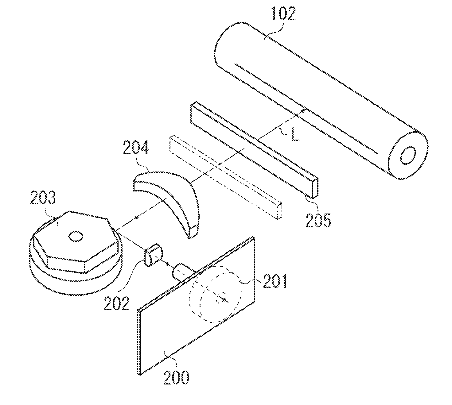
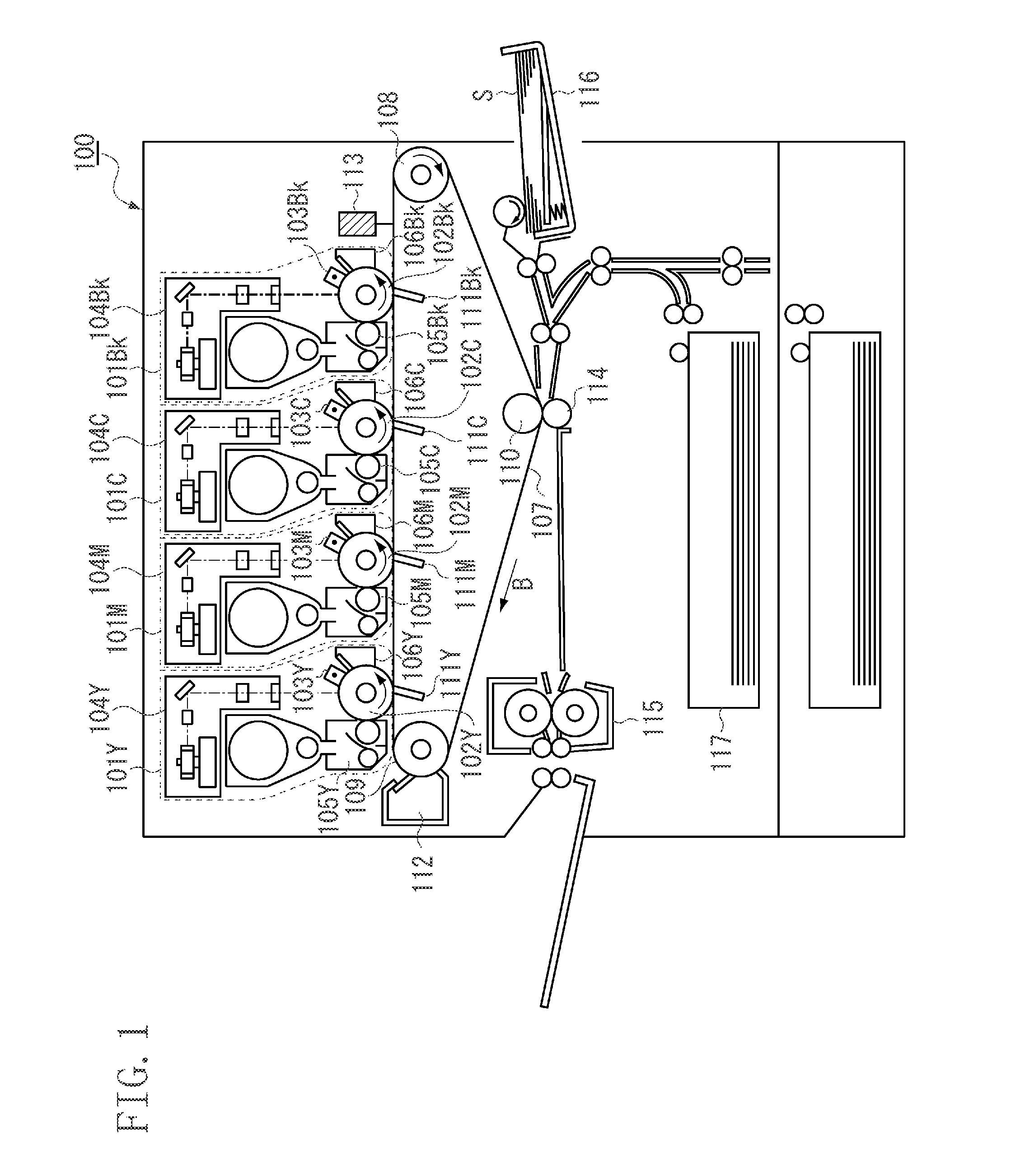
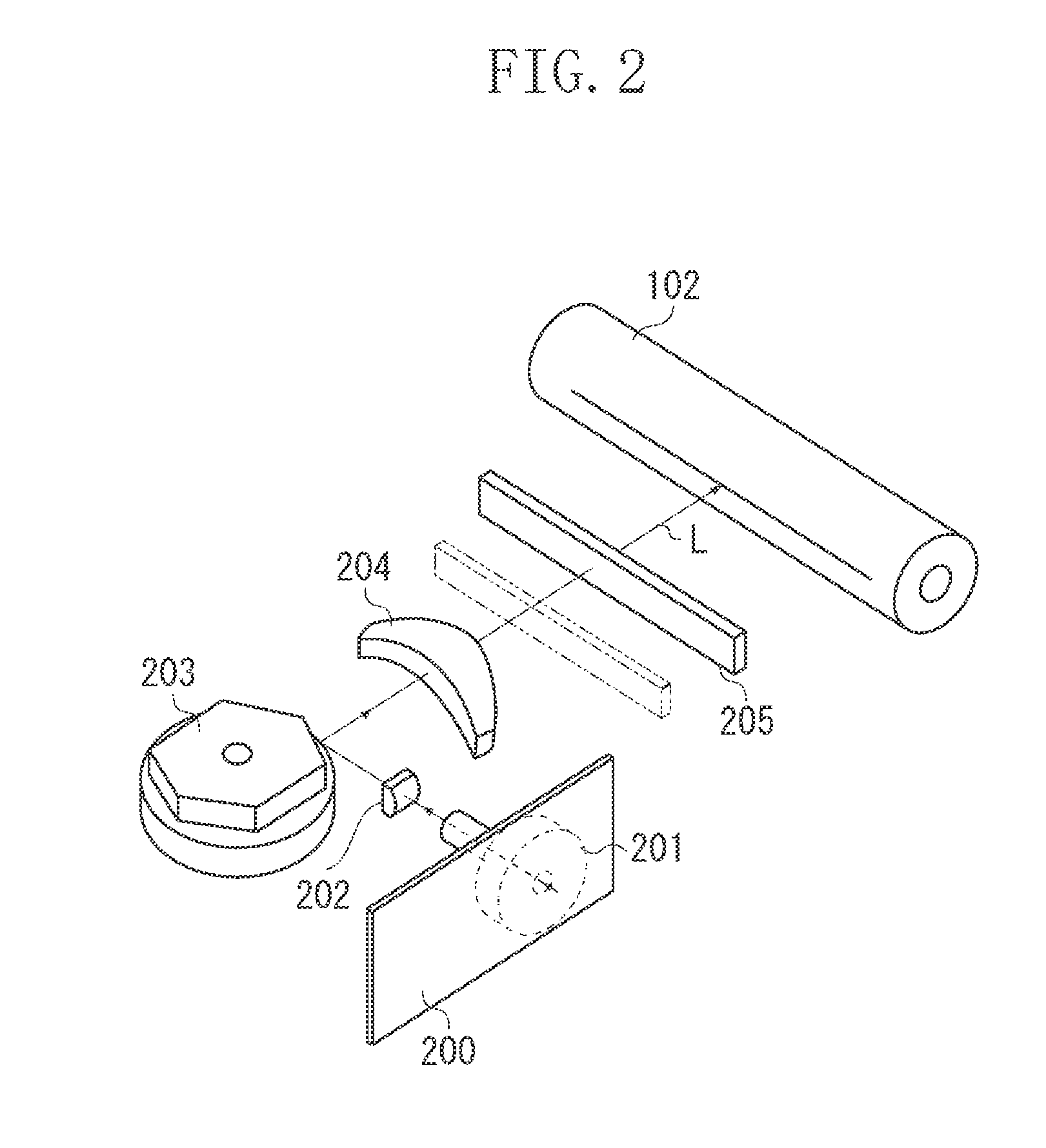
[0029]FIG. 1 is a schematic view illustrating the principal part when an optical scanning device according to a first exemplary embodiment is applied to a digital full color printer (color image forming apparatus) for forming an image using toner having a plurality of colors. FIG. 2 illustrates a schematic view of an optical scanning device in a digital full color copying machine illustrated in FIG. 1. The present exemplary embodiment will be described referring to the ...


PUM


Abstract

If inclination correction of scanning line is performed while the incident position of the laser beam is not suitable, the shape of a spot of the laser beam which forms an image on a photosensitive drum may not be uniform depending on the scanning position of the laser beam. The housing is provided with a U-shaped groove to which the convex portion of a lens hold member that holds the lens is engaged. With the position of the convex portion adjusted, the convex portion is attached and secured in the U-shaped groove. Thus, the installation position of the lens to an optical path of the laser beam is adjusted, and the lens can be rotated and adjusted in order to correct an inclination or a bending of scanning line.

Description

BACKGROUND OF THE INVENTION[0001]1. Field of the Invention[0002]The present invention relates to an optical scanning device provided on an electro-graphic image forming apparatus and an image forming apparatus including the optical scanning device.[0003]2. Description of the Related Art[0004]A conventional electro-graphic image forming apparatus scans a photoreceptor (i.e., an image bearing member) with a laser beam that an optical scanning device having a polygon mirror emits, which serves as a light source (i.e., a deflect and scan unit), and forms an electrostatic latent image on the photoreceptor. Then, the image forming apparatus develops the electrostatic latent image with a toner, and transfers and fixes the toner image on a recording medium, thereby forming an image on the recording medium.[0005]In such an image forming apparatus, a displacement of a laser beam occurs as to its irradiation position due to an installation error and insufficiency of manufacturing accuracy of a...

Claims


Application Information

Patent Timeline
Patent Type & Authority Applications(United States)
IPC IPC(8): B41J2/435G02B26/08
CPCB41J2/471G02B26/125G02B7/023
Inventor SAKURAI, YUUTA
Owner CANON KK
Why Eureka
Try Eureka