Display device, electronic apparatus, and projection imaging apparatus

a technology of electronic equipment and display device, which is applied in the direction of mountings, polarising elements, instruments, etc., can solve the problems of reducing contrast, damage to the polarization member, and inability to display images, and achieve the effect of high visual angle quality

Inactive Publication Date: 2011-03-03
SEIKO EPSON CORP
View PDF7 Cites 25 Cited by
  • Summary
  • Abstract
  • Description
  • Claims
  • Application Information

AI Technical Summary

Benefits of technology

[0018]With such a configuration, it is hard for the sunlight reflected from the inclination face of the prism or the sunlight transmitted through the prism and reflected from the display face of the display panel to overlap with the output direction of the display light. That is, the display on the display panel is prevented from being hardly seen by the influence of the sunlight reflection. The prism is provided on the display face, and thus it is possible to view an image in a state where optical characteristics such as contrast are optimal when viewing the display panel from the output direction of the display light, even when the output direction of the display light deviates from the normal line direction of the display face. In other words, it is possible to view the image with stable optical characteristics, as compared with the case of viewing the display panel in a state where there is no prism in a direction deviating from the normal line direction.Application 2
[0036]With such a configuration, it is hard to be affected by the sunlight reflection in a predetermined visual angle range, and it is possible to provide the projection imaging apparatus by which a projection image with high visual angle quality can be obtained.

Problems solved by technology

For example, in JP-A-2007-65011, it is described that when a liquid crystal display is used as the display unit, a polarization member is damaged by the sunlight, and at worst, an image cannot be displayed.
In JP-A-2007-65011, a part of the sunlight is reflected and removed by the transreflective member, but there is a problem in that most of the light is transmitted through the transreflective member, is reflected from the surface of the liquid crystal cell, and overlaps with the display light, thereby decreasing contrast.
In JP-A-2007-148092, a mechanism to pivot the optical member is necessary, and a structure thereof is complicated.
For example, when a liquid crystal display device is used as the display unit and the display unit is provided at an angle from the sunlight which is transmitted through the optical member, there is a problem that a real visual angle range of the liquid crystal display device may deviate from a range in which the optimal contrast can be obtained.
With such a configuration, it is hard for the sunlight reflected from the inclination face of the prism or the sunlight transmitted through the prism and reflected from the display face of the display panel to overlap with the output direction of the display light.

Method used


Image

  • Display device, electronic apparatus, and projection imaging apparatus
  • Display device, electronic apparatus, and projection imaging apparatus
  • Display device, electronic apparatus, and projection imaging apparatus

Examples


first embodiment

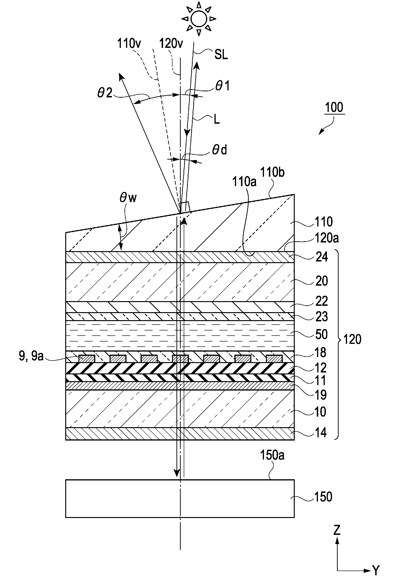
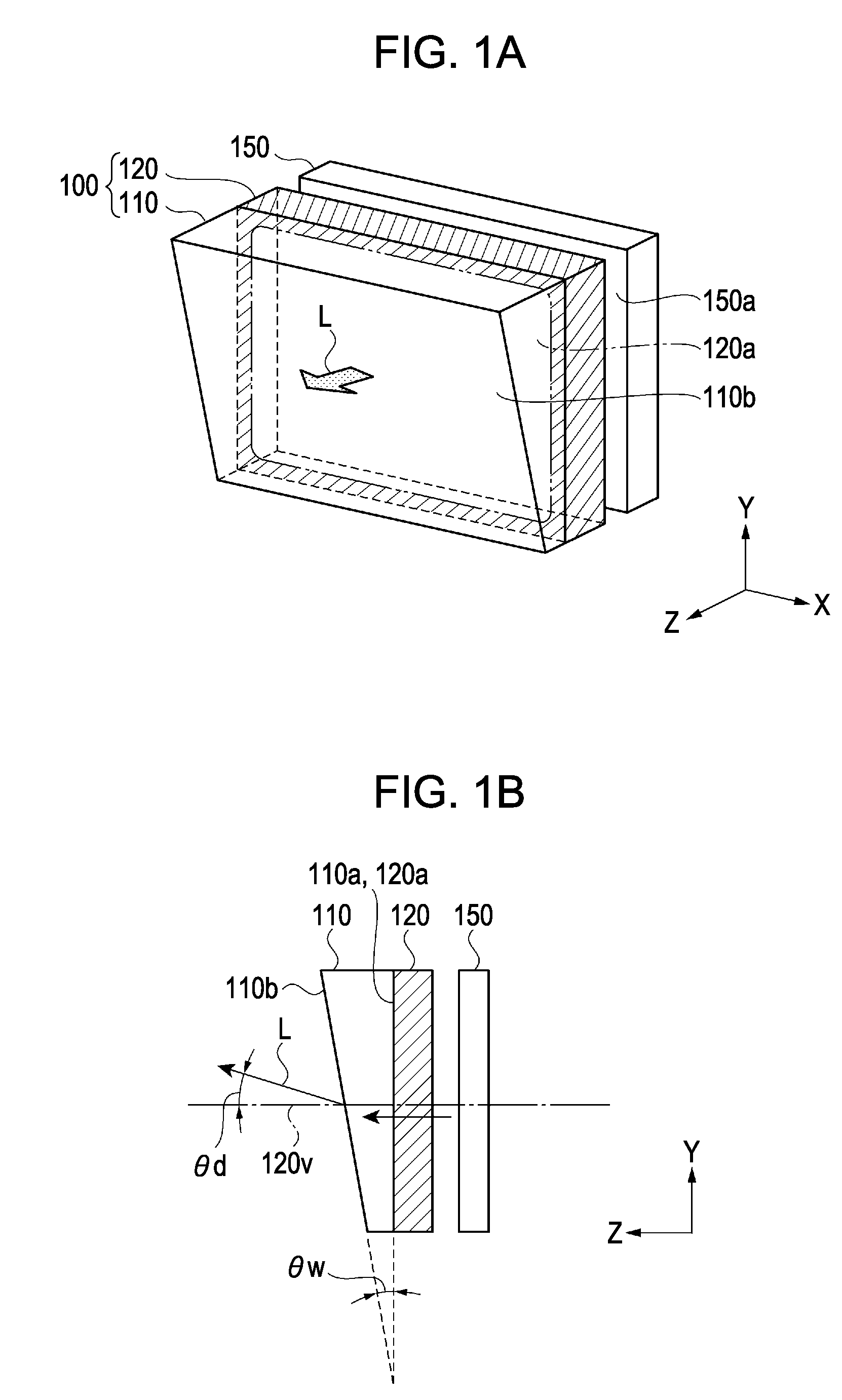
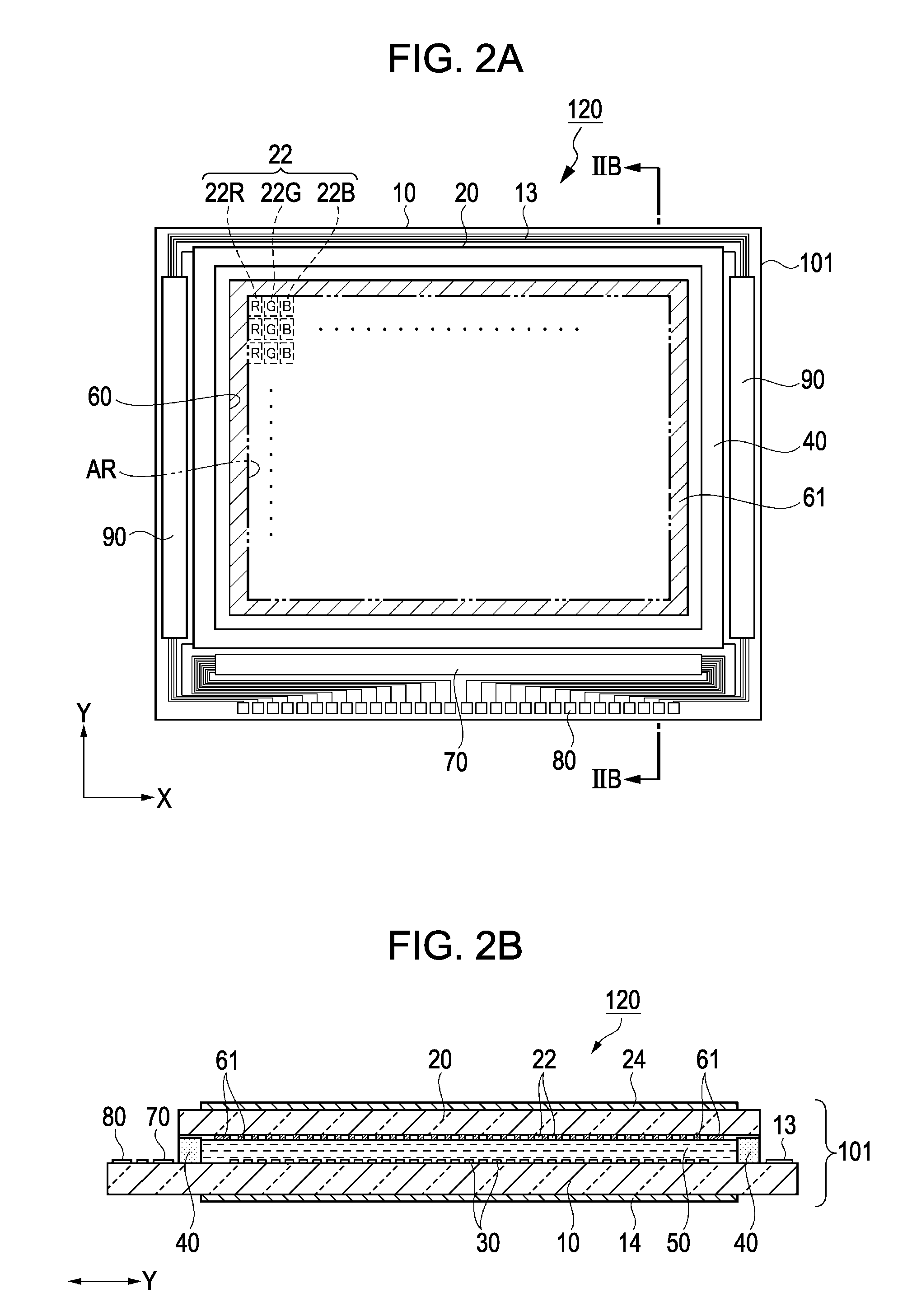
[0057]A display device according to the embodiment will be described with reference to FIG. 1A to FIG. 6. FIG. 1A is a schematic perspective view illustrating a configuration of the display device, FIG. 1B is a schematic cross-sectional view illustrating the display device, FIG. 2A is a schematic plan view illustrating a configuration of a display panel, FIG. 2B is a schematic cross-sectional view illustrating the display panel, FIG. 3 is a schematic plan view illustrating a configuration of pixels, FIG. 4 is a schematic cross-sectional view of main parts illustrating a structure of pixels, FIG. 5A is a schematic view illustrating an optical design condition in the display panel, FIG. 5B is a schematic view illustrating an optical design condition in the display panel, FIG. 5C is a schematic view illustrating an optical design condition in the display panel, and FIG. 6 is a schematic cross-sectional view illustrating an influence of sunlight in the display device.

[0058]As shown in F...

second embodiment

[0142]Next, a display device according to a second embodiment will be described with reference to FIG. 10. FIG. 10 is a schematic cross-sectional view illustrating a configuration of the display device according to the second embodiment. The same reference numeral and sign are given to the same configuration as the display device 100 of the first embodiment, and detailed description thereof is not repeated.

[0143]As shown in FIG. 10, basically, the display device 200 of the second embodiment has the same configuration as the display device 100 of the first embodiment, but there are differences in the following points.

[0144]The surface of the opposite substrate 20 opposed to the liquid crystal layer 50 is the display face 120a, and the prism 110 is disposed to come into close contact with the display face 120a. The polarization plate 24 as a polarization element on the side to which the sunlight SL is input is attached to the inclination face 110b of the prism 110.

[0145]The polarizati...

third embodiment

[0149]Next, a display device according to a third embodiment will be described with reference to FIG. 11A, FIG. 11B, and FIG. 12. FIG. 11A is a schematic perspective view illustrating a configuration of the display device of the third embodiment, FIG. 11B is a front view illustrating the display device of the third embodiment, and FIG. 12 is a schematic cross-sectional view illustrating a configuration of the display device of the third embodiment. The same reference numeral and sign are given to the same configuration as the display device 100 of the first embodiment, and detailed description thereof is not repeated.

[0150]As shown in FIG. 11A, the display device 300 has a display panel 120 and a prism 115 provided on the display face 120a of the display panel 120. The display panel 120 is a light receiving type, and is illuminated by the lighting device 150 provided on the side (rear side) opposite to the display face 120a and performs displaying. Accordingly, the display device 30...


PUM

PropertyMeasurementUnit
inclination angleaaaaaaaaaa

Abstract

A display device includes a display panel, and a prism that is installed on a display face of the display panel and has an inclination face inclined from the display face. An inclination angle of the inclination face of the prism with respect to the display face is set such that an output angle of display light output from the display face and transmitted through the prism is equal to or more than a small angle of an incident angle and a reflection angle of sunlight with respect to the inclination face based on a normal line of the display face.

Description

[0001]The entire disclosure of Japanese Patent Application No. 2009-201336, filed Sep. 1, 2009 is expressly incorporated by reference herein.BACKGROUND[0002]1. Technical Field[0003]The present invention relates to a display device, an electronic apparatus provided with display device, and a projection imaging apparatus.[0004]2. Related Art[0005]As the display device, a head-up display (HUD) has been developed which is installed in a vehicle to project an image displayed on a display unit to a windshield of the vehicle.[0006]In such a head-up display, it has been known that sunlight entering the display unit through the windshield of the vehicle has various influences.[0007]For example, in JP-A-2007-65011, it is described that when a liquid crystal display is used as the display unit, a polarization member is damaged by the sunlight, and at worst, an image cannot be displayed.[0008]In consideration of the problem, in JP-A-2007-65011, a transreflective member, which transmits display ...

Claims


Application Information

Patent Timeline
Patent Type & Authority Applications(United States)
IPC IPC(8): G02F1/1335G02B27/02G02B5/04G02B5/30G03B21/14
CPCG03B21/14G03B21/28G03B21/60G02B5/04G02B5/045G02B27/0101G02B2027/012
Inventor OKUMURA, OSAMU
Owner SEIKO EPSON CORP
Why Eureka
Try Eureka