Coupling apparatus for dividing receiving and transmitting signals and control method thereof

a technology of receiving and transmitting signals and coupling apparatus, which is applied in the direction of waveguide type devices, duplex signal operation, instruments, etc., can solve the problems of deteriorating the performance of the receiving signal, the inability to isolate and the difficulty in identifying the rfid tag signal, etc., to achieve the effect of maximizing the isolation effect of the leakage signal of the transmitting unit to the receiving uni

Active Publication Date: 2011-03-03
INTELLECTUAL DISCOVERY CO LTD
View PDF15 Cites 31 Cited by
  • Summary
  • Abstract
  • Description
  • Claims
  • Application Information

AI Technical Summary

Benefits of technology

[0023]Furthermore, in the present invention, an isolation effect of a leakage signal of a transmitting unit to a receiving unit can be maximized while adaptively changing an attenuation value of a variable attenuator.

Problems solved by technology

In this case, since the transmitting signal is mixed with a signal generated by the RFID tag being transferred to the RFID reader (i.e., the mixed signal is received by the RFID reader), it is difficult to identify an RFID tag signal.
In a case where only one antenna is used, because an intensity of a transmitting signal is much larger than that of a receiving signal in the RFID reader, leakage of a transmitting signal from a transmitting unit to a receiving unit cannot be isolated.
The leakage of the transmitting signal to the receiving unit deteriorates the performance of the receiving signal.
However, when a frequency less than 1 GHz is used in the apparatus 100, for example, when a used frequency ranges from 860 MHz to 960 MHz, the apparatus 100 has a demerit that a circulator is very large and its cost is high.
In the two cases, a leakage of a transmitting signal from a transmitting unit to a receiving unit cannot be completely isolated.
Consequently, transmission power consumption occurs.

Method used


Image

  • Coupling apparatus for dividing receiving and transmitting signals and control method thereof
  • Coupling apparatus for dividing receiving and transmitting signals and control method thereof
  • Coupling apparatus for dividing receiving and transmitting signals and control method thereof

Examples


modified example of embodiment 1

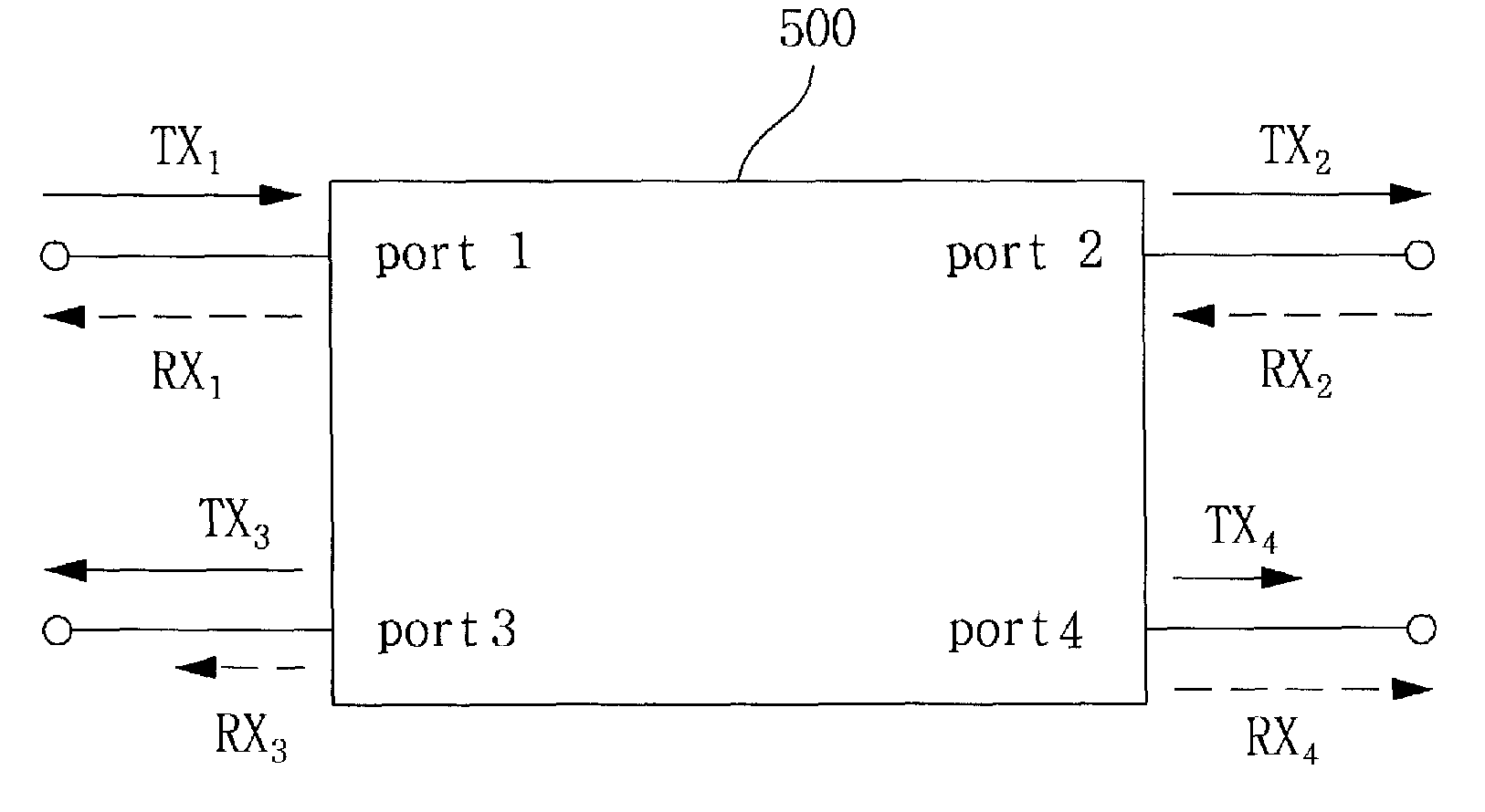
[0064]FIG. 12 is a block diagram illustrating an RF transmitting unit 604 with a coupling apparatus 610 using a high frequency transformer 211 in place of a directional coupler 210 being an example of the four-port circuit 500 in accordance with an embodiment of the present invention.

[0065]The coupling apparatus 610 of FIG. 12 includes a high frequency transformer 211, an attenuator 630, and a subtracter 670. The high frequency transformer 211 includes four ports, namely, port 1, port 2, port 3, and port 4. The relationship between respective ports is the same as in FIG. 5. Since port 1 and port 2 form a through path, when a transmitting signal TX1 from the transmitting unit 120 is input to port 1, a signal TX2 attenuated due to an insertion loss is output to port 2 (equation 1). Since port 1 and port 4 are coupled with each other, when a transmitting signal TX1 from the transmitting unit 120 is input to port 1, a coupled signal TX4 is output to port 4 (equation 2). Since port 1 and...

embodiment 2

Adaptive Change of Attenuation Value

[0069]FIG. 13 is a block diagram illustrating an RF transceiver 1300 using a variable attenuator 1330 capable of variably controlling an attenuation value of an attenuator in accordance with an embodiment of the present invention.

[0070]FIG. 14 is a block diagram illustrating an RF transceiver 1400 using a variable attenuator 1330 capable of variably controlling an attenuation value of an attenuator in accordance with another embodiment of the present invention.

[0071]Upon a usage of the variable attenuator 1330, although characteristics of the four-port circuit 500 or other components such as a PCB are changed, a desired isolation performance can be achieved. The RF receiving unit 1300 of FIG. 13 includes an antenna 140 transmitting and receiving an RF signal, a transmitting unit 120 converting a baseband signal into an RF transmitting signal TX1, a coupling apparatus 1301, a receiving unit 1340 receiving an output of the coupling apparatus 1301 as...

embodiment 2-1

[0073]The RF transceiver 1300 of FIG. 13 includes the transmitting unit 120, the receiving unit 1340, the coupling apparatus 1301, the antenna 140, and the baseband unit 660.

[0074]The coupling apparatus 1301 includes a four-port circuit 500 and a variable attenuator 1330 capable of variably controlling an attenuation value.

[0075]The receiving unit 1340 includes a low-noise amplifier 1341, an RSSI measuring unit 1342, and an attenuator control unit 1343 controlling an attenuation value of a variable attenuator 1330 based on the measured RSSI.

[0076]A transmitting signal TX1 provided to the transmitting unit 120 is input to port 1 of the four-port circuit 500, the antenna 140 is connected to port 2 thereof, and port 4 thereof is connected to an input terminal of the variable attenuator 1330. The low-noise amplifier 1341 included in the receiving unit 1340 substracts and amplifies outputs RX3 and TX3 of the port 3, and outputs RX5 and TX5 of the variable attenuator 1330. The RSSI measur...


PUM


Abstract

The present invention is directed to reducing leakage of a transmitting signal to a receiving unit in a wireless communication system with a transmitting unit and the receiving unit sharing an antenna. A coupling apparatus for dividing a radio frequency (RF) transmitting signal and an RF receiving signal in a transceiver with a transmitting unit and a receiving unit sharing an antenna, includes: a four-port circuit having port 1, port 2, port 3, and port 4, a through path being formed between the port 1 and the port 2, a first signal input to the port 1 being coupled to the port 4, a second signal input to the port 2 being coupled to the port 3, and an isolation path being formed between the port 1 and the port 4 and between the port 2 and the port 3; and an attenuator attenuating and outputting a signal output from the port 3 of the four-port circuit, and the RF transmitting signal is input to the port 1 of the four-port circuit, the RF receiving signal is input to the port 2 of the four-port circuit, and outputs of the attenuator and the port 4 of the four-port circuit are provided the receiving unit. Leakage of a transmitting signal of a transmitting unit to a receiving unit in a communication system sharing an antenna can be isolated. Furthermore, an isolation effect of a leakage signal of a transmitting unit to a receiving unit can be maximized while adaptively changing an attenuation value of a variable attenuator.

Description

CROSS-REFERENCE TO RELATED PATENT APPLICATIONS[0001]The present application claims priority under 35 U.S.C. §119 to Korean Patent Application Serial Number 10-2009-0081805, filed Sep. 1, 2009, the entirety of which is hereby incorporated by reference.FIELD OF THE INVENTION[0002]The present invention relates to wireless communication, and more particularly to technology capable of reducing leakage of a transmitting signal to a receiving unit in a wireless communication system with a transmitting unit and the receiving unit sharing an antenna.BACKGROUND OF THE INVENTION[0003]One example of a communication system for transmitting and receiving signals is a radio frequency identification (RFID) system. RFID is technology that automatically recognizes data stored in a tag, a label, or a card with a microchip using radio frequency by a reader.[0004]RFID technology causes an RFID reader to read an RFID tag information. In a case of a passive RFID tag, there is no a need for a separate powe...

Claims


Application Information

Patent Timeline
Patent Type & Authority Applications(United States)
IPC IPC(8): H04B1/44H04B1/48
CPCG06K7/0008H01P1/22H04B1/56H04B1/44
Inventor YI, JINSUNG
Owner INTELLECTUAL DISCOVERY CO LTD
Why Eureka
Try Eureka