Power distribution method and network topology method for smart grid management, and apparatus therefor

a smart grid and distribution method technology, applied in the direction of instruments, process and machine control, material dimension control, etc., can solve the problems of large waste of electricity, deterioration of energy efficiency, and vulnerability of smart grid in terms of extensibility, operability so as to improve the extensibility, flexibility, and security of smart grid management, and flexibly adjust the amount of electric power supply

Inactive Publication Date: 2011-03-03
ELECTRONICS & TELECOMM RES INST
View PDF4 Cites 32 Cited by
  • Summary
  • Abstract
  • Description
  • Claims
  • Application Information

AI Technical Summary

Benefits of technology

[0012]The present invention has been made in an effort to provide a method which can improve power distribution efficiency by defining a network topology configuration among apparatuses constituting a smart grid in order to increase the extensibility, flexibility, and security of a smart grid management and efficiently managing a smart grid through the defined network topology configuration, and a power distribution apparatus.
[0033]According to the exemplary embodiments of the present invention, the following effects can be acquired.
[0034]It is possible to improve the extensibility, flexibility, and security of smart grid management through a network topology configuration between devices constituting the smart grid.
[0035]Further, since a power producer can determine an electric power production status and an electric power usage status of the power consumer through the defined network topology configuration, the power producer can flexibly adjust the electric power supply amount. In addition, it is possible to perform flexible management in which electricity is stored and thereafter, is supplied in a time zone in which power consumption is large and to prevent a failure of the smart grid caused due to an overload.

Problems solved by technology

However, an amount of wasted electricity is also large, as a result, energy efficiency is deteriorated.
However, in the smart grid that is currently being introduced, a network topology related to smart grid management is not considered in detail and as a result, the smart grid is vulnerable in terms of extensibility, operability, and security of the smart grid.

Method used


Image

  • Power distribution method and network topology method for smart grid management, and apparatus therefor
  • Power distribution method and network topology method for smart grid management, and apparatus therefor
  • Power distribution method and network topology method for smart grid management, and apparatus therefor

Examples


Embodiment Construction

[0042]The present invention will be described below with reference to the accompanying drawings. Herein, the detailed description of a known function and configuration that may make the purpose of the present invention unnecessarily ambiguous in describing the spirit of the present invention will be omitted. Exemplary embodiments of the present invention are provided so that those skilled in the art may more completely understand the present invention. Accordingly, the shape, the size, etc., of elements in the figures may be exaggerated for explicit comprehension.

[0043]Detailed means and exemplary embodiments of the present invention will be described with reference to the accompanying drawings for describing the present invention in detail.

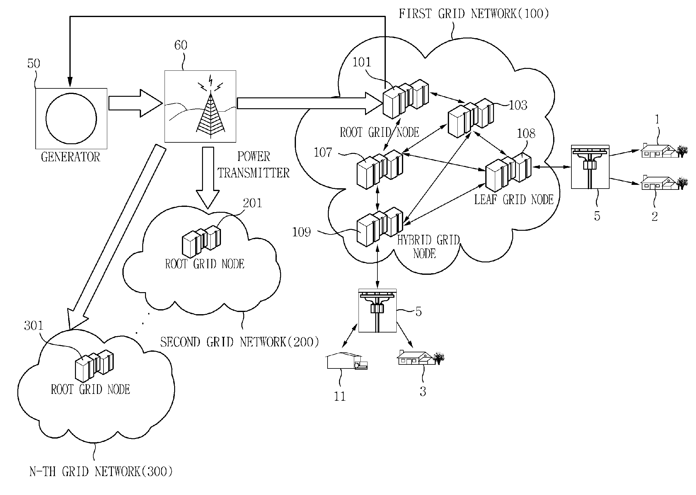
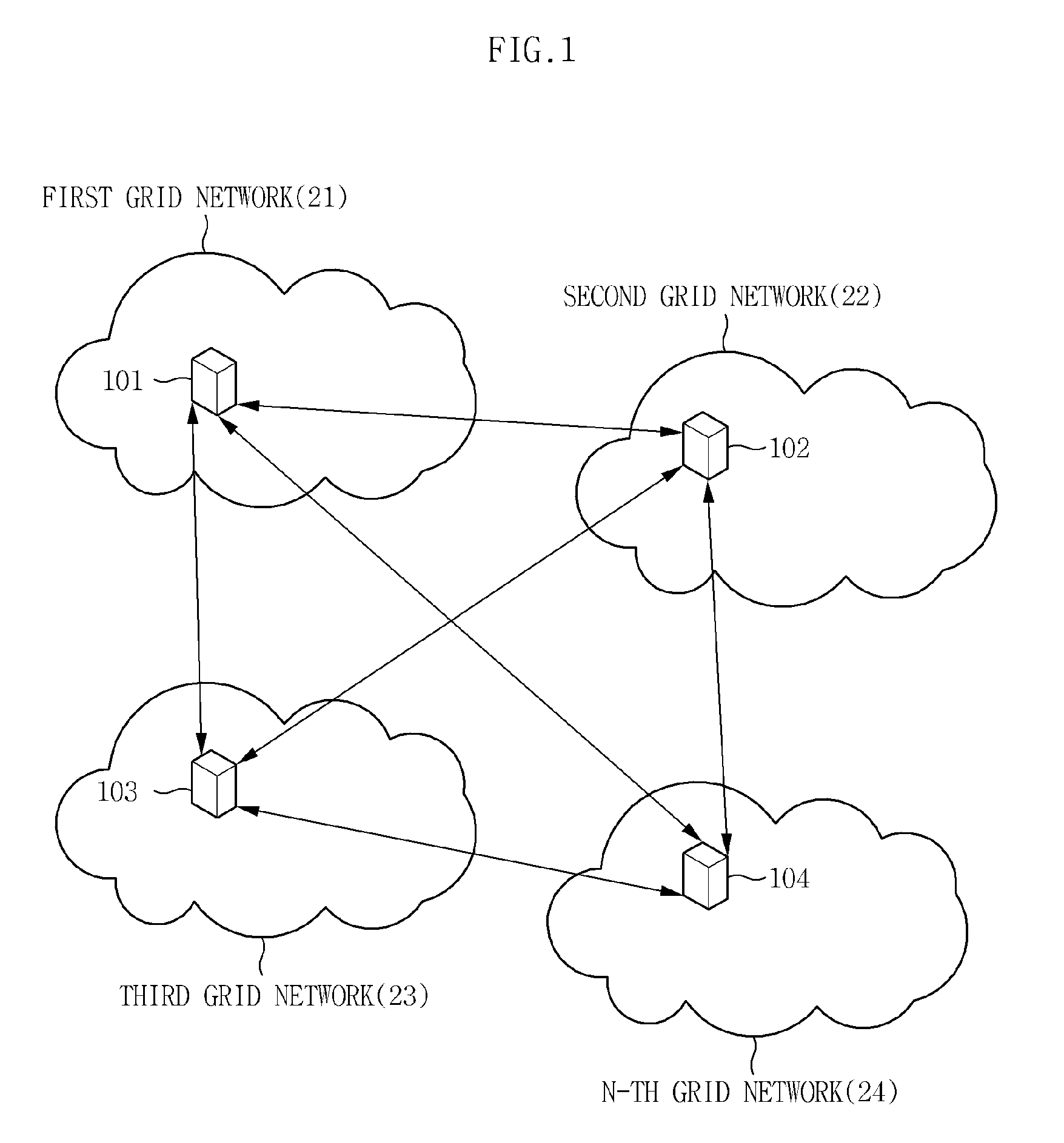
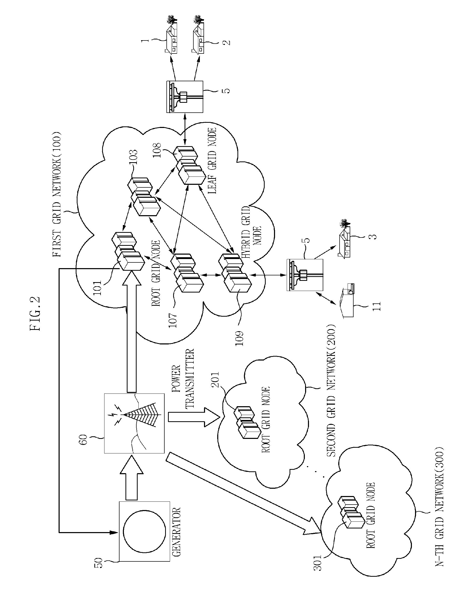
[0044]FIG. 1 is a diagram referenced for describing a network topology of a smart grid according to an exemplary embodiment of the present invention.

[0045]Referring to FIG. 1, the smart grid includes a plurality of grid networks 21, 22, 23, and 2...


PUM


Abstract

Provided is a power distribution apparatus that includes: a neighboring node information collection unit collecting power distribution amount information and physical distance information between grid nodes from neighboring grid nodes belonging to the same grid network; and a power transmission target node selecting unit allocating priorities to the neighboring grid nodes by using the power distribution amount information and the distance information and selecting a neighboring grid node having the highest priority as a neighboring power transmission grid node by comparing the priorities allocated to the neighboring grid nodes.

Description

CROSS REFERENCE TO RELATED APPLICATIONS[0001]This application claims priority to Korean Patent Application No. 10-2009-0079463 filed on Aug. 26, 2009 and Korean Patent Application No. 10-2010-0046492 filed on May 18, 2010, the entire contents of which are herein incorporated by reference.BACKGROUND OF THE INVENTION[0002]1. Field of the Invention[0003]The present invention relates to a power distribution method and a network topology method for smart grid management, and an apparatus therefore. More particularly, the present invention relates to a power distribution method and a network topology method capable of efficiently managing a smart grid while minimizing waste of electric power transmitted to general homes from a generator through a power distributor.[0004]2. Description of the Related Art[0005]A smart grid as a next-generation electric power network system improves the efficiency of a system by grafting a telecommunication technology onto the existing processes of productio...

Claims


Application Information

Patent Timeline
Patent Type & Authority Applications(United States)
IPC IPC(8): G06F19/00
CPCH02J3/06Y02E60/7853Y04S40/126H02J13/0075Y02E60/00H02J13/00024
Inventor SON, MYUNG-HEE
Owner ELECTRONICS & TELECOMM RES INST
Why Eureka
Try Eureka