Freeze plug system and method of operation

a plug and plug technology, applied in the direction of functional valve types, pipe heating/cooling, light and heating apparatus, etc., can solve the problems of high voltage cables generating heat and electrical fields, affecting the performance of cables, and leaking dielectric fluid through steel pipes

Inactive Publication Date: 2011-03-10
CONSOL EDISON OF NEW YORK
View PDF9 Cites 22 Cited by
  • Summary
  • Abstract
  • Description
  • Claims
  • Application Information

AI Technical Summary

Benefits of technology

[0010]In accordance with another embodiment of the invention, a device for generating a freeze plug is provided. The device includes a jacket and a first tube fluidly coupled to the jacket adjacent a first end. A second tube is fluidly coupled to the jacket adjacent a second end, wherein the second end is opposite the first end. A first valve is coupled to the first tube. A first temperature sensor is thermally coupled to the second tube. A controller is electrically coupled to the first temperature sensor and the first valve, the controller includes a processor that is responsive to executable computer instructions for modulating the first valve in response to a signal from the first temperature sensor such that a superheated level of a gas flowing from the jacket through the second tube is maintained.

Problems solved by technology

One issue that arises in underground installations is the heat and electrical fields generated by the high voltage cables.
During normal use over an extended period of time, leaks of dielectric fluid through the steel pipe can sometimes occur.
These leaks may be due to a number of reasons, such as shooting fluid jet from an adjacent water or steam pipe, mechanical fatigue, or corrosion for example.
It should be appreciated that the leakage of the dielectric fluid may be undesirable environmentally and result in degradation in the performance of the cable.
There is poor contact between the freeze jackets and the outside wall of the pipe.
Since the heat transfer mechanism is by conduction, poor contact between the jackets and the pipe does not help the heat transfer.
Thus large amounts of liquid nitrogen are required over an extended period of time.
Also, since these transmission cables may be located in a metropolitan area, any delays in the delivery of adequate quantities of liquid nitrogen may cause issues in forming and maintaining the freeze plugs.
This process of forming the freeze plug also results in a large block of ice forming around the outside surfaces of the freeze jackets.
While the block of ice may assist in holding the cable and freeze plug temperatures, it also lengthens the time it takes to thaw the freeze plug.
Typically, using this method, it takes 8 to 24 hours to thaw the oil around the transmission cables once the repairs have been completed.
For example, in a food processing facility, production could be halted during the repair, or in a water distribution system, water would not be delivered to end customers during the repair.

Method used


Image

  • Freeze plug system and method of operation
  • Freeze plug system and method of operation
  • Freeze plug system and method of operation

Examples


Embodiment Construction

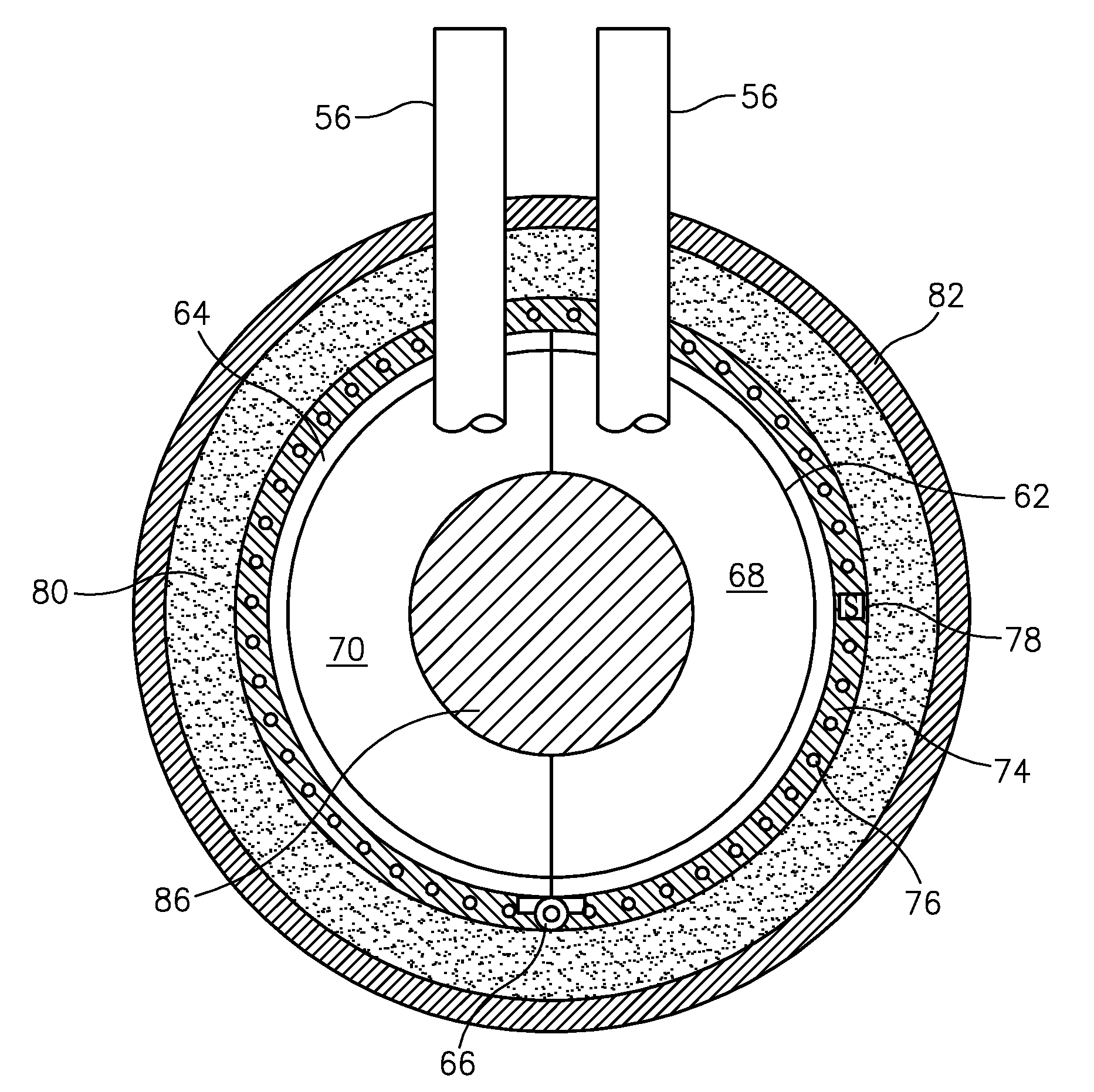
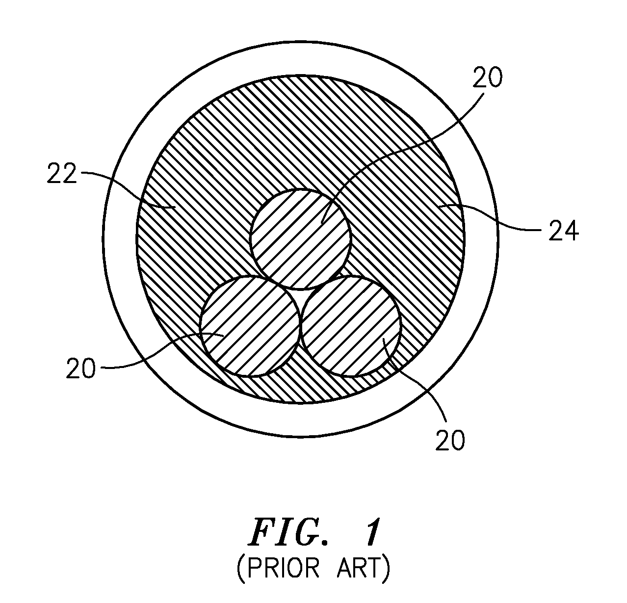
[0026]Fluid filled pipes are used in a wide variety of applications. In some applications the pipes do not include valves that allow the conduit to be segmented for maintenance or repair. Valves may not be included for a number of reasons. For example in the transmission of high voltage electrical power, the electrical power conductors 20 are housed within a pipe 22 that contains a dielectric fluid 24. The dielectric fluid 24 isolates the power conductors 20 and also helps heat transfer that is generated by the power conductors 20 during operation. Since a valve would interfere with the power conductors 20, fluid filled high voltage transmission lines operate contiguously over long distances with no mechanism for segmenting the sections of pipe.

[0027]It should be appreciated that high voltage transmission lines may operate contiguously for many miles. To drain the entire line would be a lengthy and costly procedure. Further, service to customers along the entire length of the transm...


PUM


Abstract

A freeze and thaw system using knowledge-based hardware and methodology is provided for repair of oil-filled pipes. Liquid nitrogen is boiled off inside freeze jackets installed over the pipe, exiting in a superheated vapor state. Liquid nitrogen flow rates, controlled by the temperature controllers, are based on the requirements of the freeze process to maintain a desired level of superheat. The freeze operation is divided into distinct phases each with a different nitrogen superheated exhaust temperature. At the end of the repair, electric heaters wrapped over the pipe proceed to thaw the frozen oil. The heater controller thaws the frozen plugs based on an embedded time versus temperature protocol. The freeze prevention heaters are wrapped over the freeze jackets to prevent ice formation over the cold freeze jackets while the freeze plug is formed and maintained. This technology results in less thaw and freeze time at reduced liquid nitrogen usage.

Description

BACKGROUND OF THE INVENTION[0001]The present invention relates generally to a system for freezing and thawing stationary oil in a section of a pipe to create a frozen plug. As these underground pipes do not incorporate any isolation valves, the plugs serve that function. This allows repair in the oil-filled pipes that also contain high voltage electric cables. At the end of the repairs, the frozen plug is thawed to initiate oil flow through the pipe.[0002]Fluid filled pipes are used in a variety of applications such as equipment used in food processing systems, water delivery systems, cooling of High Voltage electric cables, electrical distribution systems as well as the exploration, delivery and processing of oil, natural gas and their end products. The fluid may be in the pipes for a variety of purposes, such as delivery of the fluid to an end point, to transfer or deliver thermal energy to a system, or to isolate a component within the pipe from the external environment.[0003]One...

Claims


Application Information

Patent Timeline
Patent Type & Authority Applications(United States)
IPC IPC(8): F25J1/00F16L53/00H05B1/02
CPCH05B3/40F16L55/103Y10T137/7737
Inventor MALIK, PAULCARBONARA, JOSEPHGAUGHAN, JOHN T.MALIK, HANS K.
Owner CONSOL EDISON OF NEW YORK
Why Eureka
Try Eureka