Humidity control and ventilation system

a humidity control and ventilation system technology, applied in the direction of heating types, instruments, separation processes, etc., can solve the problems of complex configuration of humidity control and ventilation systems with dehumidifying units as a main part, and achieve the effect of simple configuration

Inactive Publication Date: 2011-03-10
DENSO CORP
View PDF4 Cites 39 Cited by
  • Summary
  • Abstract
  • Description
  • Claims
  • Application Information

AI Technical Summary

Benefits of technology

[0011]Since on-off of a heat exchange function between the intake air and the discharge air is switched in the above-described ventilation system, two bypass passages and the damper for opening and closing the bypass passages are necessary. Thus, the configuration of the ventilation system may become complex. However, according to the configuration of claim 10, on-off of a heat exchange function can be switched with a simple configuration.

Problems solved by technology

Thus, for securing sufficient humidity control performance, there is a problem that a configuration of a humidity control and ventilation system having a dehumidifying unit as a main part becomes complex.

Method used


Image

  • Humidity control and ventilation system
  • Humidity control and ventilation system
  • Humidity control and ventilation system

Examples


first embodiment

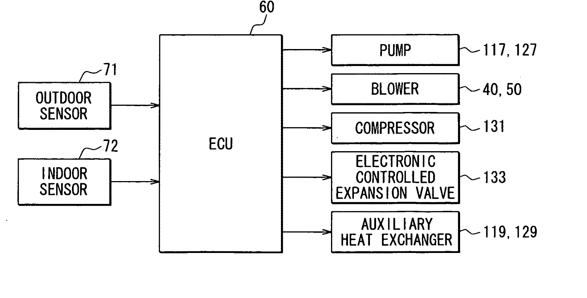
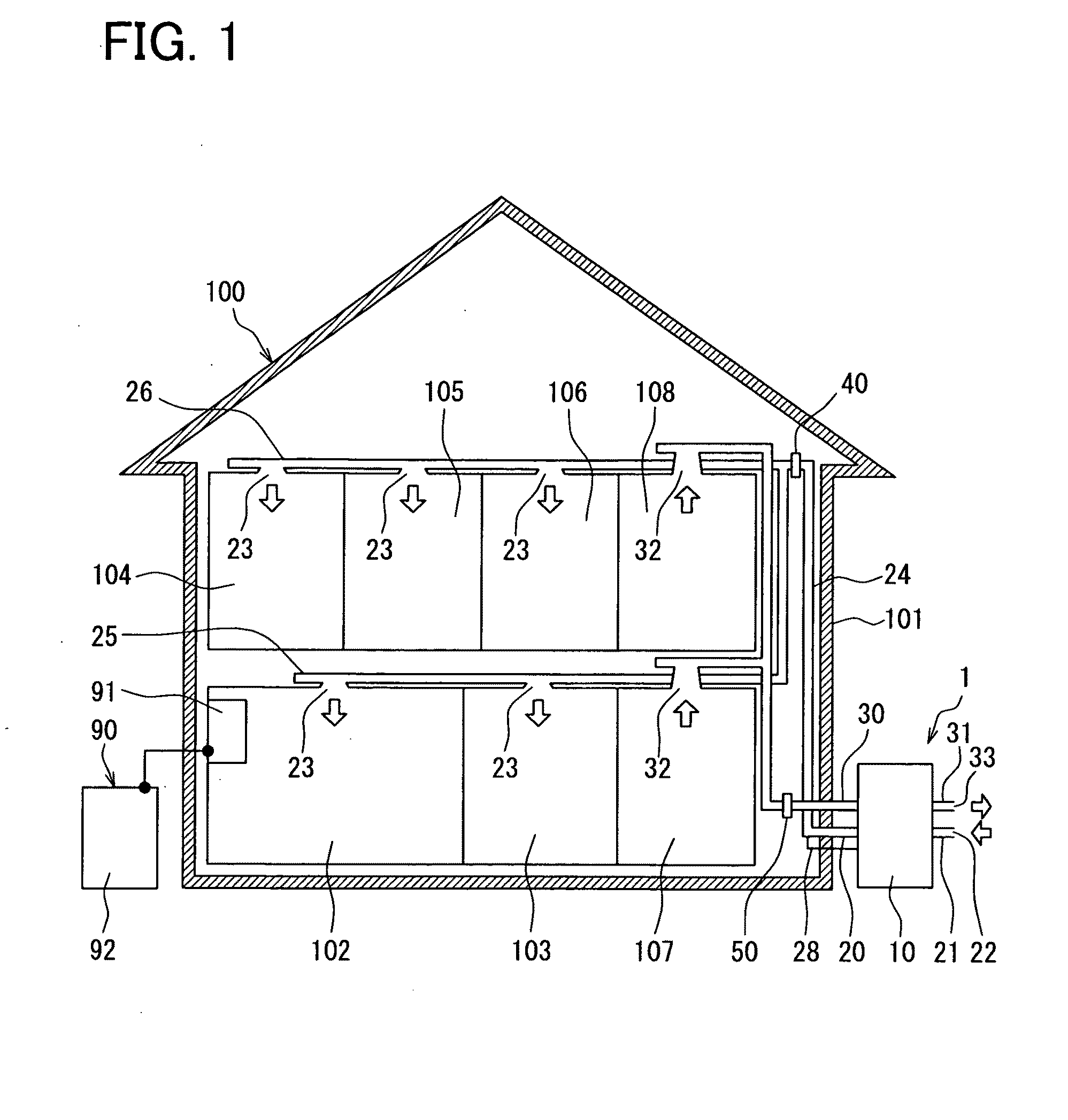
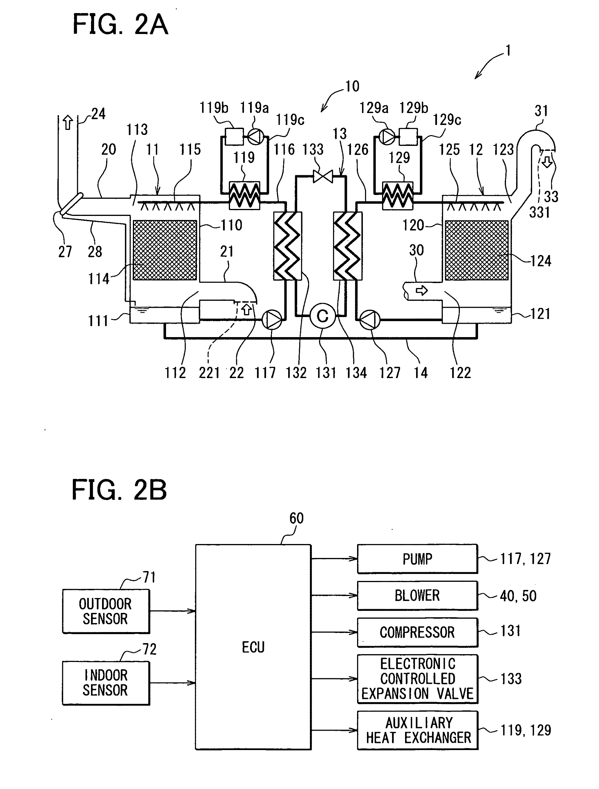
[0029]FIG. 1 is a system configuration diagram showing an air-conditioning system including a humidity control and ventilation system 1 according to the first embodiment of the present invention. FIG. 2A is a schematic diagram showing a configuration of a main part of the humidity control and ventilation system 1.

[0030]As shown in FIG. 1, the humidity control and ventilation system 1 arranged in a building 100 includes an absorption-type humidity controller 10, an intake pipe 21, an intake duct 20, an exhaust duct 30, and an exhaust pipe 31. The humidity controller 10 uses, for example, lithium chloride aqueous solution as hygroscopic liquid. The intake pipe 21 has an exterior inlet port 22 at an upstream end thereof and conducts external air into the humidity controller 10. The intake duct 20 has an interior outlet port 23 at a downstream end thereof and conducts air, which is humidity controlled by the humidity controller 10, into an internal space. The exhaust duct 30 has an inte...

second embodiment

[0084]Next, the second embodiment of the present invention will be described with reference to FIG. 7.

[0085]A configuration of the intake duct 20 and arranged positions of the intake blower 40 and the exhaust blower 50 in the second embodiment are different from those of the first embodiment. It is to be noted that the component which is the same with that in the first embodiment is designated by the same reference numeral and a description thereof will not be repeated.

[0086]As shown in FIG. 7, in the present embodiment, the intake duct 20 is branched to the first-floor intake duct 25 in the middle of the vertical duct 24. Moreover, the intake blower 40 is arranged in the intake pipe 21 at an upstream side of the processing unit 11, and the exhaust blower 50 is arranged in the exhaust pipe 31 at a downstream side of the regenerating unit 12.

[0087]Since the first-floor intake duct 25 is branched in the middle of the vertical duct 24, the first-floor intake duct 25 does not need to be...

third embodiment

[0090]Next, the third embodiment of the present invention will be described with reference to FIG. 8.

[0091]The third embodiment is different from the first and second embodiments in that a duct-type air conditioner, which conditions air in multiple rooms simultaneously, that is, a central air conditioner, is used as the air conditioner 90 of the building in place of a room air conditioner, which conditions air in each of the rooms individually. It is to be noted that the component which is the same with that in the first and second embodiments is designated by the same reference numeral and a description thereof will not be repeated.

[0092]As shown in FIG. 8, in the present embodiment, the indoor unit 91 for the central air conditioner is arranged in the attic, and an air-conditioning intake duct 93 is extended from the indoor unit 91 to the interior outlet ports 23 formed in the respective rooms such as the living room 102, the Japanese room 103, the bedroom 104, the child's room 10...


PUM

PropertyMeasurementUnit
lengthaaaaaaaaaa
densityaaaaaaaaaa
densityaaaaaaaaaa

Abstract

A humidity control and ventilation system for a building with an absorption-type humidity controller includes an air supply passage, air discharge passage and a processing unit. The air supply passage is configured to conduct intake air from an exterior inlet port, which is located at an outside of the building, to an interior outlet port, which is located at an inside of the building. The processing unit is inserted in the air supply passage. The air supply passage includes an intake duct that is located between the processing unit and the interior outlet port, and the intake duct includes a vertically extending section, which extends in a vertical direction to create an upflow of the intake air conducted from the processing unit toward the interior outlet port.

Description

CROSS REFERENCE TO RELATED APPLICATION[0001]The present application is based on Japanese Patent Application No. 2009-208351 filed on Sep. 9, 2009, the disclosure of which is incorporated herein by reference.FIELD OF THE INVENTION[0002]The present invention relates to a humidity control and ventilation system which conditions humidity of an internal space and performs ventilation.BACKGROUND OF THE INVENTION[0003]As a related art, a humidity control and ventilation system is disclosed in JP-A-10-61979. The humidity control and ventilation system includes an intake passage for conducting external air into an internal space, an exhaust passage for exhausting internal air into an external space, a dehumidifying unit in which hygroscopic liquid absorbs moisture from air flowing through the intake passage for dehumidification, and a regenerating unit in which moisture is released from hygroscopic liquid into air flowing through the exhaust passage to regenerate the hygroscopic liquid.[0004...

Claims


Application Information

Patent Timeline
Patent Type & Authority Applications(United States)
IPC IPC(8): F24F3/14B01F3/04
CPCF24F11/0008F24F3/1417
Inventor KADOTA, SHIGERU
Owner DENSO CORP
Why Eureka
Try Eureka