
Method of producing hollow core for coaxial cable, hollow core for coaxial cable, and coaxial cable

Inactive Publication Date: 2011-03-10
UBE NITTO KASEI CO LTD
View PDF0 Cites 12 Cited by
  • Summary
  • Abstract
  • Description
  • Claims
  • Application Information

AI Technical Summary

Benefits of technology

[0033]According to the present invention, it is possible to produce a hollow core for a coaxial cable having stable electric characteristics in its longitudinal direction although the hollow core has a high hollow rate.

Problems solved by technology

However, since this layer is solid, a foaming degree (extent of foaming) of the entire coaxial cable hollow core can not be increased.
Further, a rate of an area of the skin layer occupying the entire insulator is increased, and it is difficult to produce a coaxial cable hollow core having stable electric characteristics in its longitudinal direction while keeping a high foaming degree (high hollow rate).

Method used

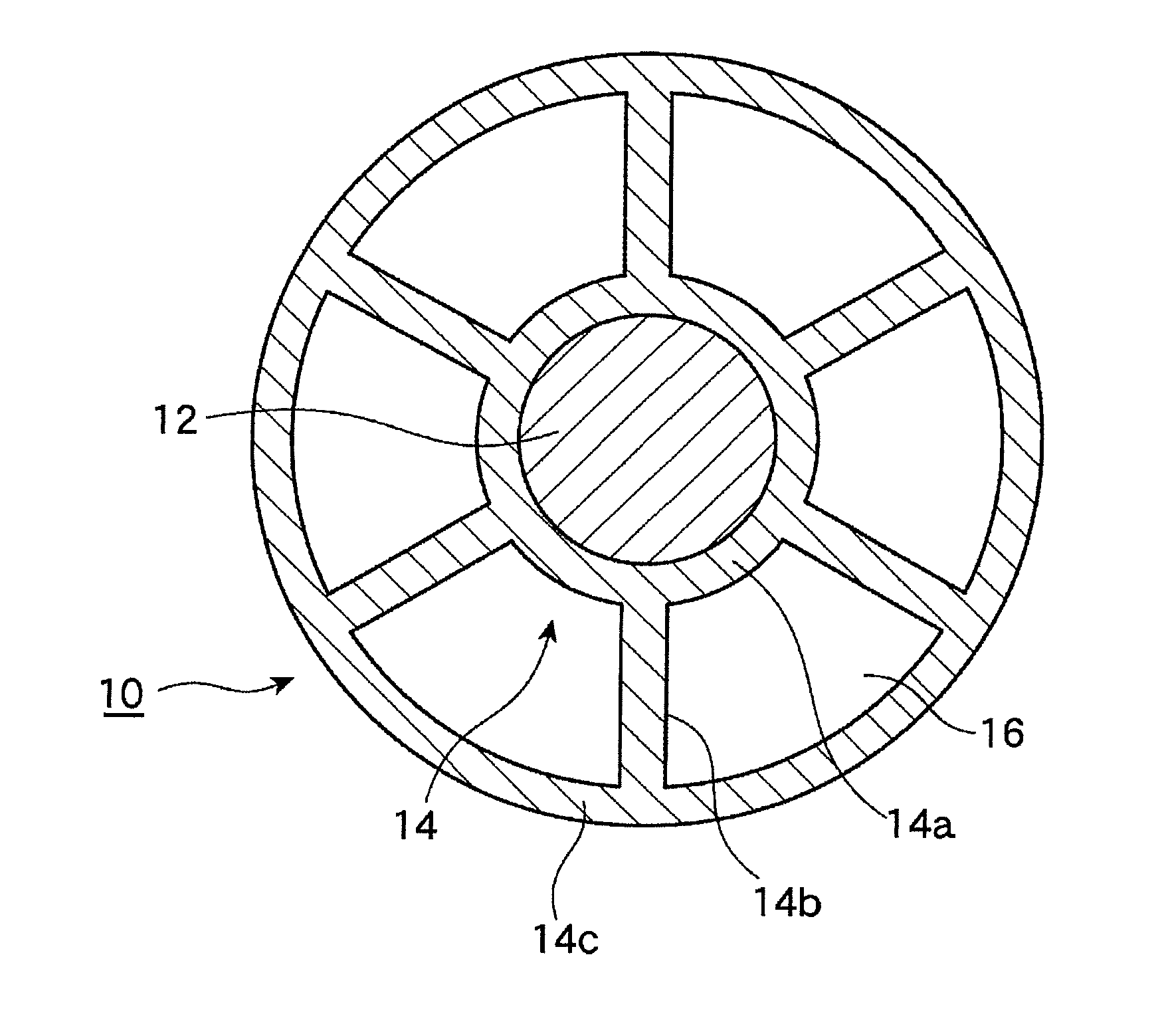
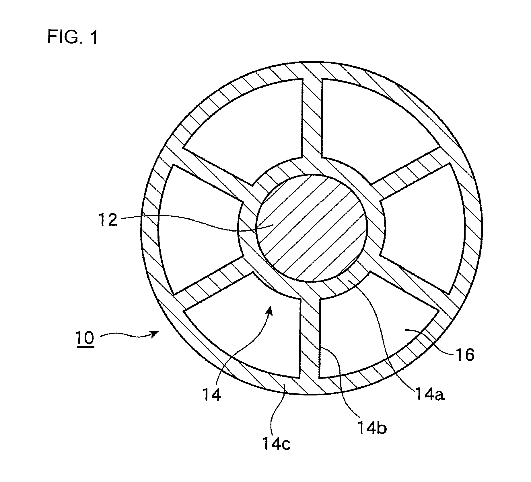
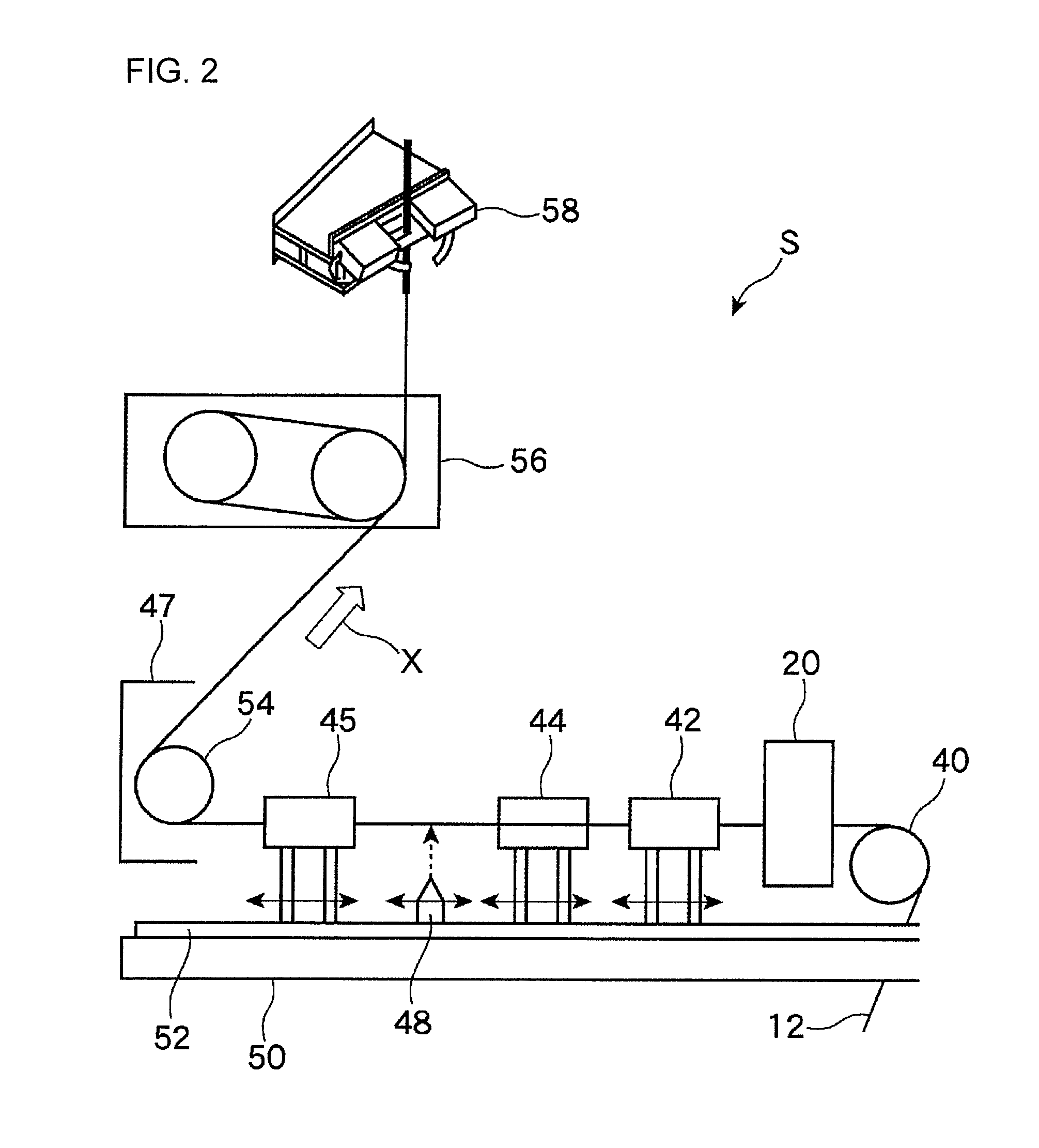

Image

  • Method of producing hollow core for coaxial cable, hollow core for coaxial cable, and coaxial cable
  • Method of producing hollow core for coaxial cable, hollow core for coaxial cable, and coaxial cable
  • Method of producing hollow core for coaxial cable, hollow core for coaxial cable, and coaxial cable

Examples


example 1

Example in which Preferable Shape can be Obtained by Heat Cylinder

[0072]The hollow core 10 was produced using the producing apparatus shown in FIG. 2.

[0073]As the inner conductor, tin-plated tin alloy wires of 7 / 0.025 mm (wires obtained by stranding seven tin-plated tin alloy wires having an outer diameter of 0.025 mm, the same as above hereinafter) were introduced into a cross head die having a temperature of 350° C., the wires were made to pass through the die 20 having an opening shown in FIG. 5 at a speed of 35 m / minute, and the wires were coated with PFA resin (“AP201SH” produced by DAIKIN INDUSTRIES, LTD., dielectric constant was 2.1, resin melting point was about 310° C.). The heating cylinder 42 (draft zone) having a length of 300 mmm and atmospheric temperature of 250° C., and the air-cooling portion 44 (air-cooling zone) having a length of 500 mm and room temperature (average temperature was 30° C.) were provided directly below the die 20. The area-drafting magnification r...

example 2

Example in which Suitable Shape is Obtained by the Heating Cylinder

[0081]Using the producing apparatus shown in FIG. 2, the hollow core 10 was produced.

[0082]As the inner conductor, tin-plated tin alloy wires of 7 / 0.025 mm (wires obtained by stranding seven tin-plated tin alloy wires having an outer diameter of 0.025 mm, the same as above hereinafter) were introduced into a cross head die having a temperature of 350° C., the wires were made to pass through the die 20 having an opening shown in FIG. 5 at a speed of 35 m / minute, and the wires were coated with PFA resin (“AP201SH” produced by DAIKIN INDUSTRIES, LTD., dielectric constant was 2.1, resin melting point was about 310° C.).

[0083]The heating cylinder 42 (draft zone) having a length of 300 mm and atmospheric temperature of 150° C., and the air-cooling portion 44 (air-cooling zone) having a length of 500 mm and room temperature (average temperature was 30° C.) were provided directly below the die 20.

[0084]The area-drafting magn...

example 3

Example in which Inner Conductor of 7 / 0.03 mm was Used

[0097]As the inner conductor, tin-plated tin alloy wires of 7 / 0.03 mm were introduced into a cross head die having a temperature of 350° C., the wires were made to pass through the die 20 at a speed of 35 m / minute, and the wires were coated with PFA resin.

[0098]The heating cylinder 42 having a length of 300 mm and atmospheric temperature of 250° C., and the air-cooling portion 44 having a length of 500 mm and room temperature (average temperature was 30° C.) were provided directly below the die 20.

[0099]The area-drafting magnification ratio was 1213 times, and a hollow core having an outer diameter of 0.24 mm was obtained.

[Evaluation of Shape]

[0100]The obtained hollow core 10 was cut and size thereof was measured. As a result, a thickness of the outer annular portion was 0.016 mm, a thickness of the rib was 0.016 mm, and a thickness of the inner annular portion was 0.018 mm.

[0101]The hollow rate of the hollow portion 16 obtained ...


PUM

PropertyMeasurementUnit
Lengthaaaaaaaaaa
Fractionaaaaaaaaaa
Fractionaaaaaaaaaa

Abstract

To produce a hollow core for a coaxial cable having high hollow rate and stable electric characteristics in its longitudinal direction. A producing method of a hollow core for a coaxial cable, the hollow core comprising: an inner conductor; and an insulating coating body including an inner annular portion for coating the inner conductor, a plurality of ribs extending radially from the inner annular portion, and an outer annular portion having an outer diameter of 0.5 mm or less for connecting outer ends of the ribs with each other; in which the hollow core includes a plurality of hollow portions surrounded by the inner annular portion, the outer annular portion and the ribs, a ratio of an area of the hollow portion in the insulating portion is 40% or more, and a roundness of the outer annular portion is 96.0% or more, wherein the producing method comprises at least: a step (1) of extruding molten resin from the die that capable of forming the insulating coating body; a step (2) of heating a resin forming the insulating coating body; and a step (3) of cooling the resin forming the insulating coating body slowly at a temperature close to a room temperature.

Description

TECHNICAL FIELD[0001]The present invention relates to a producing method a hollow core for a coaxial cable, the hollow core for a coaxial cable and a coaxial cable. More particularly, the invention relates to a technique concerning a hollow core for a coaxial cable having stable electric characteristics in its longitudinal direction although the hollow core has a high hollow rate.BACKGROUND ART[0002]As information technology moves forward, a coaxial cable is also required to enhance its performance (reduction in loss, increase in transmission speed), and to enhance density (downsizing of cable). Therefore, it is required to lower a dielectric constant of an insulator, and to enhance its stability. To lower the dielectric constant of the insulator, it is effective to introduce air into an insulating coating resin, and a foam-type resin (PE, PFA, PTFE or the like) is used.[0003]To prevent a hollow portion of the hollow core from being crushed or deformed, a skin layer (solid layer) is...

Claims


Application Information

Patent Timeline
IPC IPC(8): H01B11/18H01B7/00H01B13/20
CPCH01B11/1856Y10T29/49123H01B13/202
Inventor TANAKA, SEIJIMATSUNO, SHIGEHIROSUEMORI, MASAYA
Owner UBE NITTO KASEI CO LTD
Learn More