

Passive lossless snubber cell for a power converter
- Summary
- Abstract
- Description
- Claims
- Application Information
AI Technical Summary
Benefits of technology
Problems solved by technology
Method used
Image

Examples
Embodiment Construction
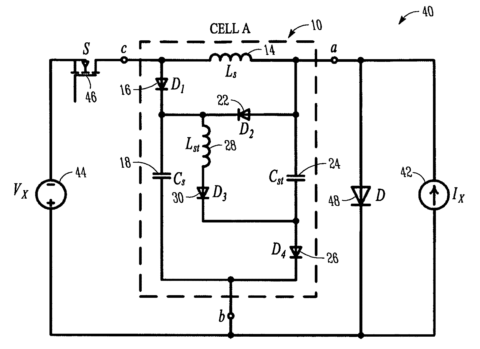
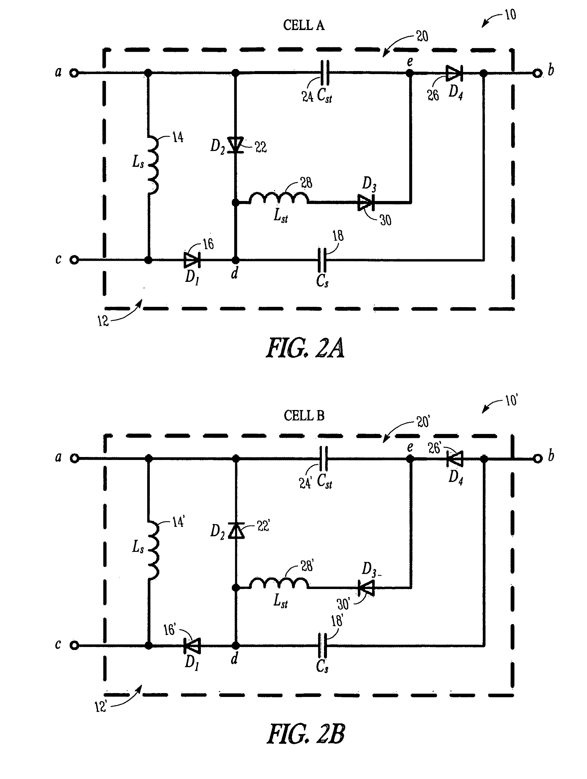
[0051]Referring to FIGS. 2a and 2b, shown are schematic circuit diagrams of first and second embodiments of a snubber cell 10, 10′ for a switched-mode power converter according to the invention. As can be readily seen from a comparison of cell A (FIG. 2a) with cell B (FIG. 2b), the major difference between cells A and B is that of the direction of current flowing through node a and thus the polarity of some of the components within the circuit. Otherwise, cells A and B have the same general construction and configuration of components.
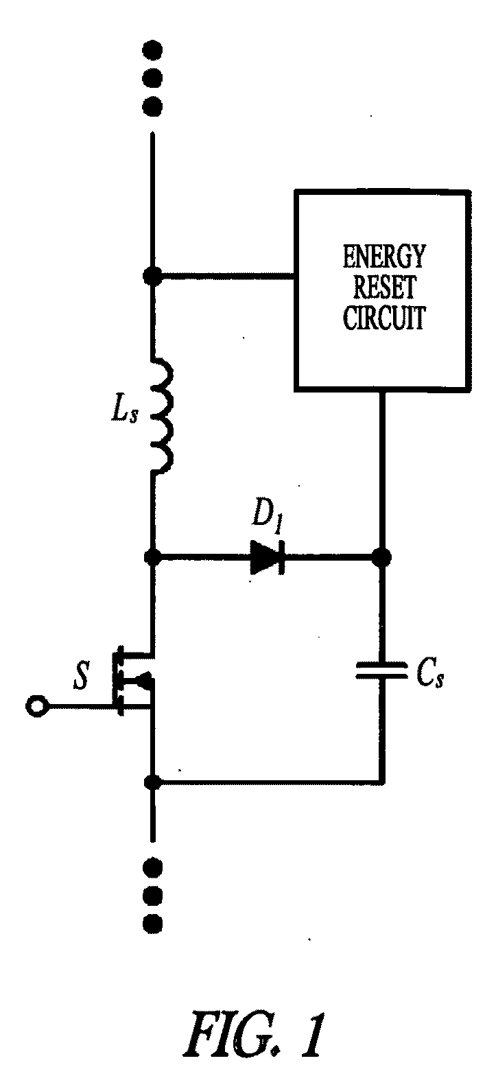
[0052]Referring to FIG. 2a, it can be seen that cell A 10 comprises an energy absorbing circuit 12 consisting of a snubber inductor Ls 14 arranged between first and third terminals / nodes a and c of the snubber cell 10, and a first diode D1 16 and a snubber capacitor Cs 18 arranged in series between the third terminal c and a second terminal b of said snubber cell 10. The snubber cell 10 also comprises an energy resetting circuit 20 coupled to said ener...
PUM
 Abstract
Description
Claims
Application Information