Optical scanning device and image forming apparatus

a scanning device and image forming technology, applied in optics, instruments, electrical devices, etc., can solve the problems of difficult to reduce the distance from the optical deflector to the separation unit, the thickness of the optical scanning device is increased, and the disadvantage of lowering the height of the device body

Inactive Publication Date: 2011-03-10
RICOH KK
View PDF66 Cites 22 Cited by
  • Summary
  • Abstract
  • Description
  • Claims
  • Application Information

AI Technical Summary

Benefits of technology

[0018]It is an object of the present invention to at least partially solve the problems in the conventional technology.

Problems solved by technology

Therefore, the thickness of the optical scanning device is increased in the direction perpendicular to the plane where the scanning positions of the photosensitive drums are arranged, and this configuration is thereby disadvantageous to lower the height of the device body.
Secondly, an imaging unit needs to be provided between the optical deflector and the separation unit, which makes it difficult to reduce the distance from the optical deflector to the separation unit, and thus, there is a limit on miniaturization of the optical scanning device.
However, in the conventional optical scanning device of a one-side scanning system in which a plurality of light fluxes incident on a light deflector 2001 are deflected on the same surface of the optical deflector for scanning, a separation direction for the light fluxes is the rotation axis direction of the optical deflector, and thus, there is not much space on the side of the surface to be scanned in a writing housing, which causes a size (t′) to be larger.
In addition, when a reflection angle at a separation mirror is large, wavefront aberration of the light fluxes may be degraded because of low surface accuracy of the separation mirror.

Method used


Image

  • Optical scanning device and image forming apparatus
  • Optical scanning device and image forming apparatus
  • Optical scanning device and image forming apparatus

Examples


first embodiment

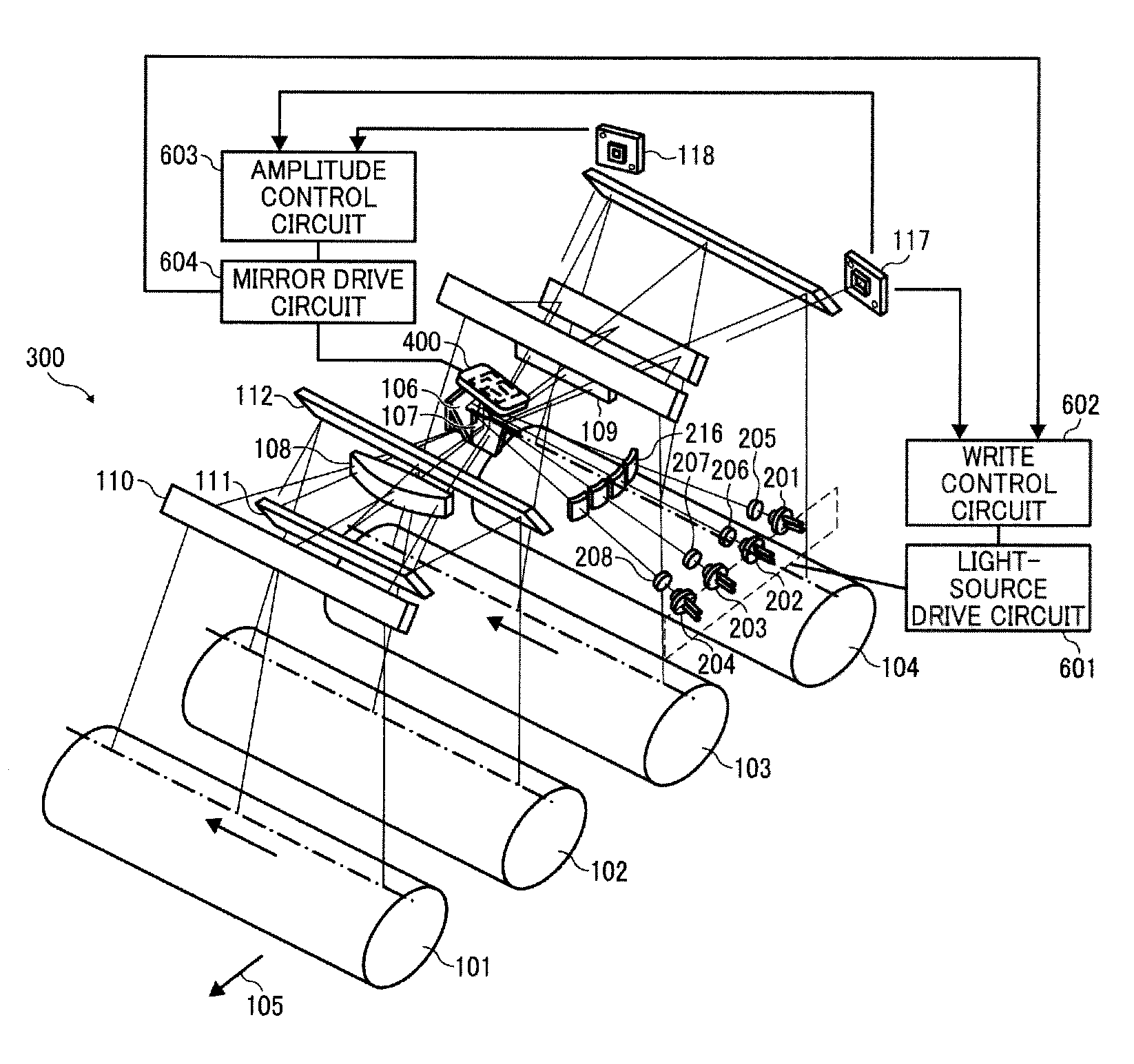
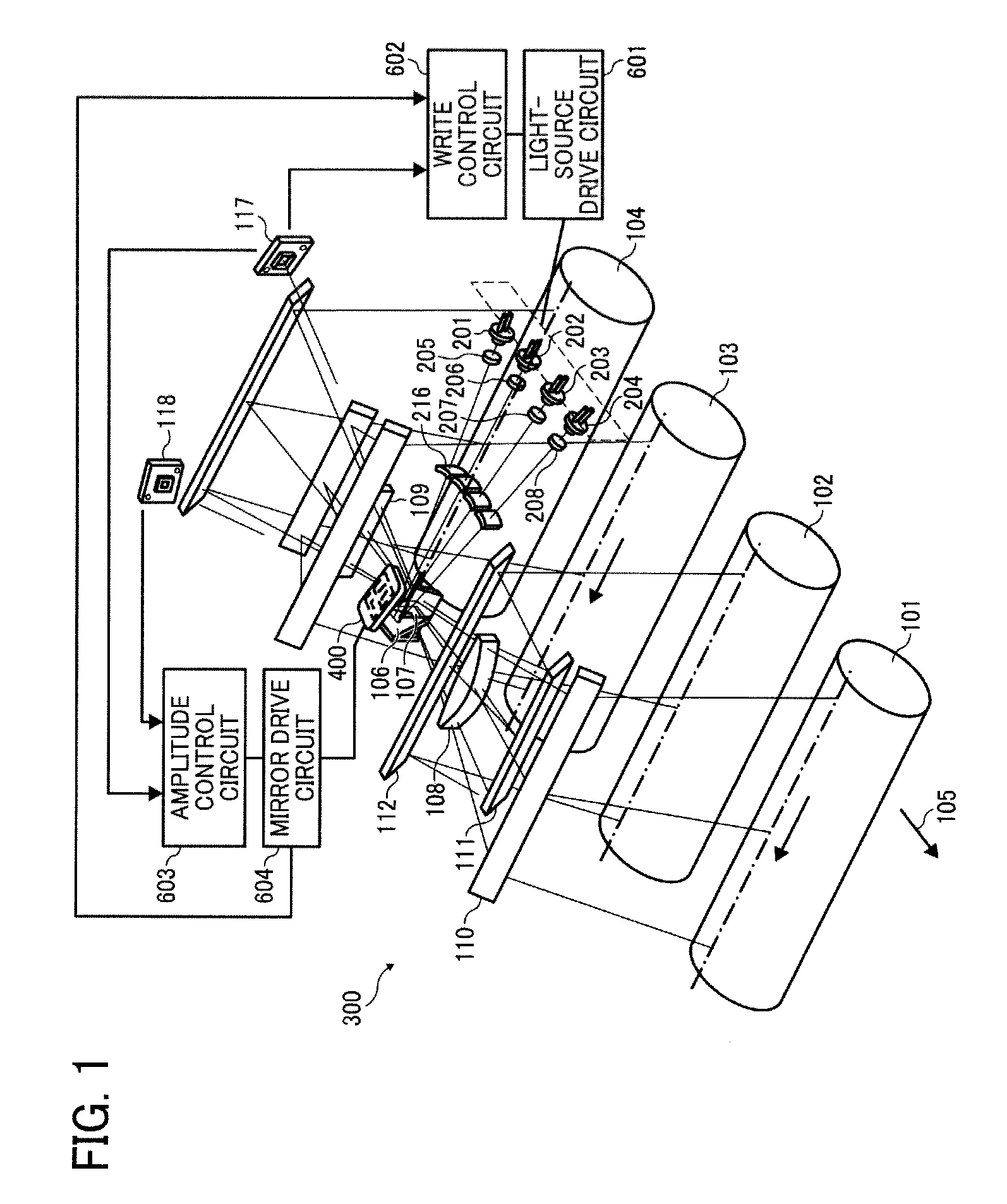
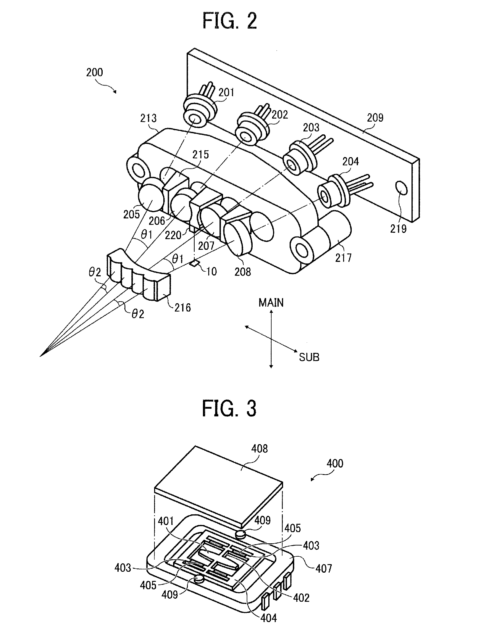
[0053]FIG. 1 represents a configuration of an optical scanning device that scans four stations by a single oscillating mirror. FIG. 2 is a perspective view of a configuration of a light source module 200. FIG. 3 represents a configuration of an oscillating mirror module 400 as a deflecting unit. The present embodiment represents an example of using the oscillating mirror that generates rotational torque by a piezoelectric actuation system as a deflecting unit.

[0054]In FIG. 1 and FIG. 2, reference numerals 101 to 104 represent photosensitive drums; 105: a movement direction of a transfer body; 106: an incidence mirror; 107: a separation mirror; 108 and 109: scanning lenses; 110 to 112: bending mirrors; 201 to 204: semiconductor lasers; 205 to 208: coupling lenses; 216: a cylindrical lens; 117: a synchronization detection sensor; 118: a termination detection sensor; 300: an optical scanning device; 601: a light-source drive circuit; 602: a write control circuit; 603: an amplitude cont...

second embodiment

Second Embodiment (1)

[0149]FIG. 16 is a perspective view of an optical scanning device that scans four stations by using a micromirror using a resonance phenomenon for the optical deflector. An optical path diagram of an optical path from a light source unit to a separation mirror 1112 viewed from an observation point Q in FIG. 16 is shown in FIG. 17, while an optical path diagram representing the downstream of the deflector and viewed from an observation point P in FIG. 16 is shown in FIG. 18. Terms “upstream and downstream” mentioned here indicate an earlier point and a later point in the optical path along which beams 1201 to 1204 pass from their emission from light sources to reaching photosensitive drums 1101 to 1104, respectively.

[0150]As shown in FIG. 16, the optical scanning device for scanning the photosensitive drums is configured integrally. Beams emitted from light sources corresponding to the four photosensitive drums 1101, 1102, 1103, and 1104 arranged at an equal spac...

second embodiment (

3)

[0185]FIG. 24 is a perspective view of an optical scanning device in which an oblique incidence angle of light on the micromirror 1106 (an incidence angle in the rotation axis direction A of the micromirror 1106) is made finite and which is further provided with second scanning lenses 1122 to 1125 based on the configuration of the second embodiment (1). An optical path diagram representing the downstream of a deflector and viewed from an observation point P in FIG. 24 is shown in FIG. 25. The relation between the rotation axis A of the micromirror 1106 and the separation of the beams 1201 to 1204 are arranged in the same manner as these of the previously described embodiment. There is adopted a method of widening oblique incidence angles of the beams 1201 to 1204 by the cylindrical lens group 1113, however, if there is any extra space in the layout of the light source units and if there is no problem such as interference even if the oblique incidence angles are kept as they are, a...


PUM


Abstract

An oscillating mirror module as a deflecting unit is disposed so that a movable mirror faces a plane where image carriers are arranged. A plurality of light source units are disposed within a plane parallel to the plane where the image carriers are arranged so that main light fluxes of light beams emitted from the light sources form predetermined angles with each other. The oscillating mirror module includes an incidence mirror that bends a plurality of light beams emitted from the light source units to direct the light beams to the movable mirror, and a separation mirror that separates the light beams scanned by the movable mirror into two opposite directions with respect to a cross-section including a surface normal of the movable mirror and perpendicular to the rotation axis of the movable mirror. A light collecting unit collects light beams so that output optical axes of the light beams corresponding to the light source units intersect on a surface of the movable mirror of the deflecting unit.

Description

CROSS-REFERENCE TO RELATED APPLICATIONS[0001]The present application claims priority to and incorporates by reference the entire contents of Japanese Patent Application No. 2009-204939 filed in Japan on Sep. 4, 2009 and Japanese Patent Application No. 2009-247629 filed in Japan on Oct. 28, 2009.BACKGROUND OF THE INVENTION[0002]1. Field of the Invention[0003]The present invention relates to an optical scanning device and an image forming apparatus such as a copier, a printer, a facsimile, a plotter, or a multifunction printer provided with at least one of these, which includes the optical scanning device.[0004]2. Description of the Related Art[0005]A deflecting unit using silicon micromachining has been studied in recent years, and there is proposed a system in which an oscillating mirror and a torsion bar rotatably supporting the oscillating mirror are integrally formed on a Si substrate, as disclosed in Japanese Patent No. 2924200 and Japanese Patent No. 3011144.[0006]Japanese Pate...

Claims


Application Information

Patent Timeline
Patent Type & Authority Applications(United States)
IPC IPC(8): H04N1/04G02B26/10
CPCG02B26/105G02B27/42H04N1/506G02B27/4244G02B27/4227
Inventor SOEDA, MASAHIRONAKAMURA, TADASHIKOJIMA, AKIRANAKAJIMA, TOMOHIRO
Owner RICOH KK
Why Eureka
Try Eureka