Real-time motion tracking using tomosynthesis

a technology of tomosynthesis and real-time motion, applied in the direction of material analysis using wave/particle radiation, instruments, etc., can solve the problems of reducing the quality of ct images, unable to collect sufficient quantity of ct image data for image reconstruction, and inability to generate ct images with sufficient quality or accuracy

Active Publication Date: 2011-03-10
VARIAN MEDICAL SYSTEMS
View PDF15 Cites 33 Cited by
  • Summary
  • Abstract
  • Description
  • Claims
  • Application Information

AI Technical Summary

Problems solved by technology

However, currently available apparatus that supports CT may not be able to generate tomographic images with sufficient quality or accuracy in part due to intra-fraction motion caused by inadvertent patient shifts or natural physiological processes.
For example, breathing or expelling gas through the rectum has each been shown to cause degradation of quality in CT images.
This is because collecting a sufficient quantity of CT image data for image reconstruction may take a long time, and therefore may not be performed at a fast enough rate to provide sufficiently current information to adjust the treatment radiation beam.
However, finding the pixel coordinates of a high density marker in a single X-ray projection can be difficult.
Overlaying anatomy and external structures are an important source of failure of these techniques.
Very often, the X-ray quantum noise and scattered radiation result in the failure to detect or localize a marker using automatic image analysis algorithms.
One drawback is that most BEV imaging occurs at MV energies, which is less dose-efficient than imaging at kilo-volt (kV) energies.
Another drawback is that, if high density fiducial markers are used, the markers may not be exposed to BEV at all times, thus causing treatment to be interrupted for purposes of repositioning the multi-leaf collimator blades.
Interruption of treatment is particularly undesirable for arc-therapies.
Nevertheless, the motion-related problems with full CT acquisitions still exist as can SNR and other limitations associated with acquiring a single projection radiograph for 3D point tracking.

Method used


Image

  • Real-time motion tracking using tomosynthesis
  • Real-time motion tracking using tomosynthesis
  • Real-time motion tracking using tomosynthesis

Examples


Embodiment Construction

Various embodiments are described hereinafter with reference to the figures. It should be noted that the figures are not drawn to scale. It should also be noted that the figures are only intended to facilitate the description of embodiments. They are not intended as an exhaustive description of the disclosure or as a limitation on the scope of the disclosure. In addition, an aspect described in conjunction with a particular embodiment is not necessarily limited to that embodiment and can be practiced in any other embodiments.

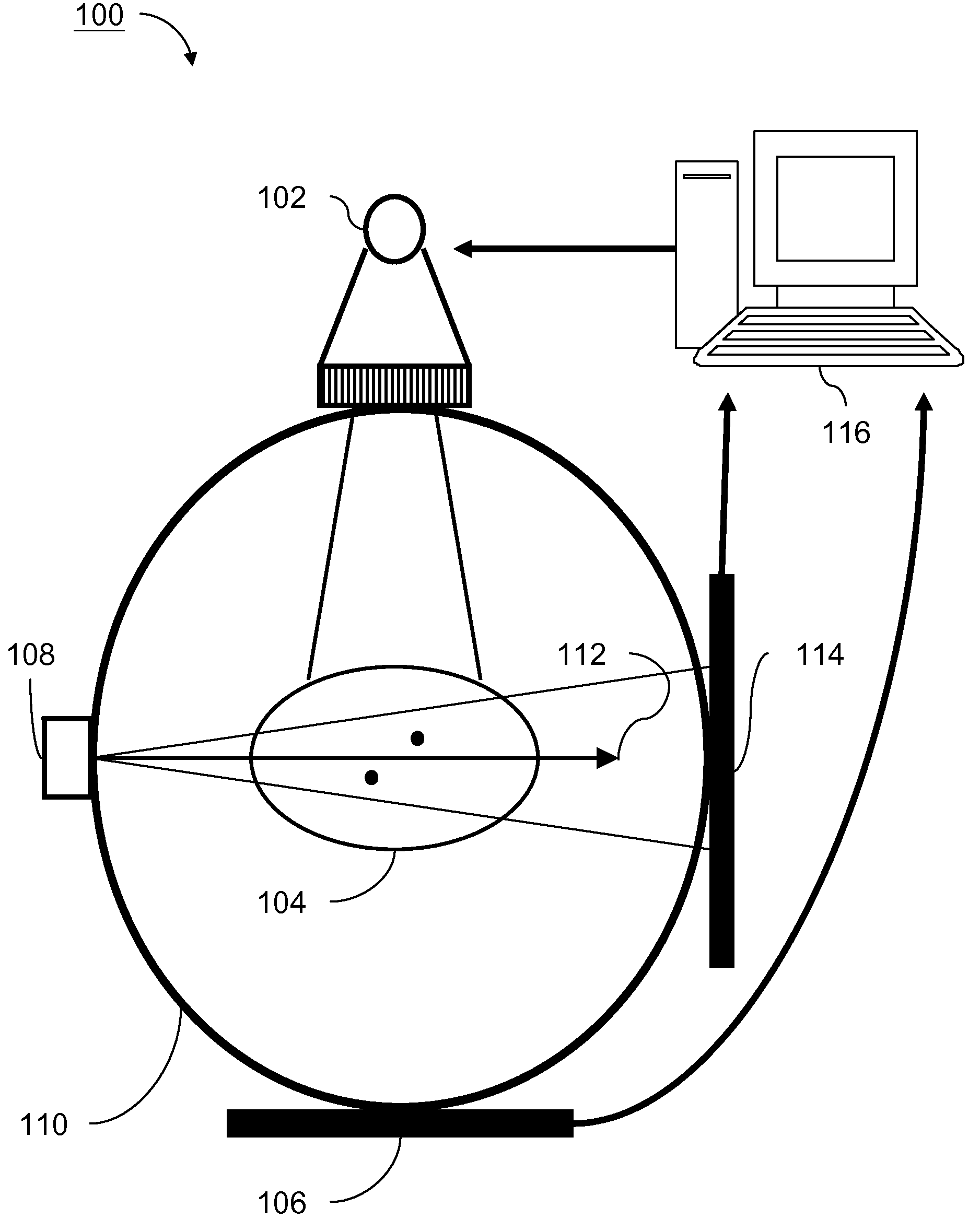
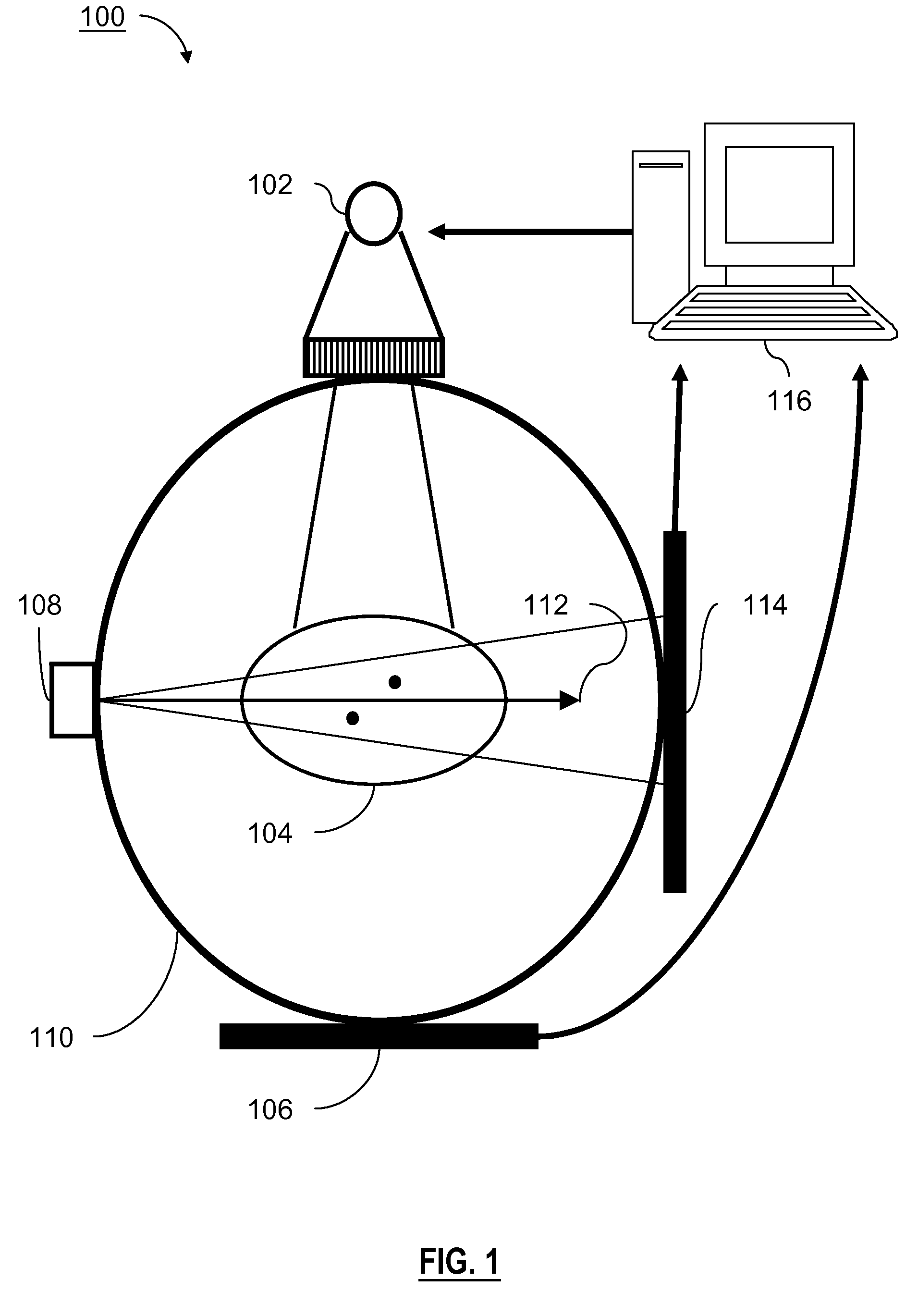
FIG. 1 is a schematic diagram illustrating a treatment radiation system 100, according to one embodiment of the disclosure. The treatment radiation system 100 includes a first radiation source 102, an electronic portal imaging device (EPID) 106, a second radiation source 108 mounted on a gantry 110, a flat panel detector 114, and a control system 116. The first radiation source 102 is aimed towards a patient 104 and to the EPID 106. The patient 104 has markers, ...


PUM

PropertyMeasurementUnit
energyaaaaaaaaaa
rotational angleaaaaaaaaaa

Abstract

One embodiment of the present disclosure sets forth a method for determining a movement of a target region using tomosynthesis. The method includes the steps of accessing a first set of projection radiographs of the target region over a first processing window defined by a first range of projection angles, accessing a second set of projection radiographs of the target region over a second processing window defined by a second range of projection angles, wherein the first processing window moves to the second processing window, and comparing a first positional information derived from the first set of the projection radiographs and a second positional information derived from the second set of the projection radiographs with the first positional information to determine the movement of the target region.

Description

BACKGROUNDUnless otherwise indicated herein, the approaches described in this section are not prior art to the claims in this application and are not admitted to be prior art by inclusion in this section.Various systems and methods exist to provide radiation therapy treatment of tumorous tissue with high-energy radiation. Many forms of radiation treatment benefit from the ability to accurately control the amount, location, and distribution of radiation within a patient's body. Such control often includes using a multi-leaf collimator to shape a radiation beam to approximate that of the tumorous region.Many existing radiation treatment procedures require a location of a target region to be determined in order to accurately register the target region relative to a radiation source before radiation is applied to the target region. Computed tomography (“CT”) is an imaging technique that has been widely used in the medical field. In a procedure for CT, an x-ray source and a detector appa...

Claims


Application Information

Patent Timeline
Patent Type & Authority Applications(United States)
IPC IPC(8): G01N23/00A61N5/10
CPCG01N23/046G01N2223/612G01N2223/419A61B6/025A61B6/027A61B6/12A61B6/4014A61B6/4085A61B6/4233A61B6/4266A61B6/4435A61B6/4452A61B6/4476A61B6/5205A61B6/5217A61N5/1049A61N2005/1054A61N2005/1061G01N23/044G16H50/30
Inventor STAR-LACK, JOSHMOSTAFAVI, HASSAN
Owner VARIAN MEDICAL SYSTEMS
Why Eureka
Try Eureka