Device and method for x-ray examination of an object for material defects by means of x-rays

Inactive Publication Date: 2011-03-10
SIEMENS AG
View PDF14 Cites 2 Cited by
  • Summary
  • Abstract
  • Description
  • Claims
  • Application Information

AI Technical Summary

Benefits of technology

[0023]The use of a multi-emitter opens up the possibility of obtaining a number of exposures for a region of the object from different directions by means of the x-ray tube given a stationary source (i.e. without the radiator traversing a trajectory), in that different emitters and/or a different beam collimation are/is set for the exposures. As in a to

Problems solved by technology

Individual two-dimensional projections have the disadvantage that no information about the object is obtained with regard to the direction of the x-ray radiation because the variable measured by the projection represents a variable integral to the path through the object.
One of these disadvant

Method used


Image

  • Device and method for x-ray examination of an object for material defects by means of x-rays
  • Device and method for x-ray examination of an object for material defects by means of x-rays
  • Device and method for x-ray examination of an object for material defects by means of x-rays

Examples


Embodiment Construction

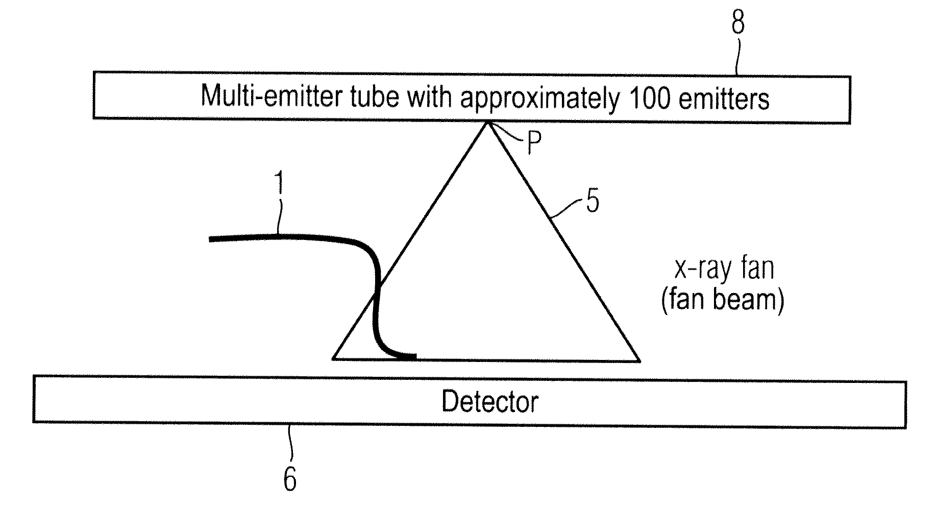
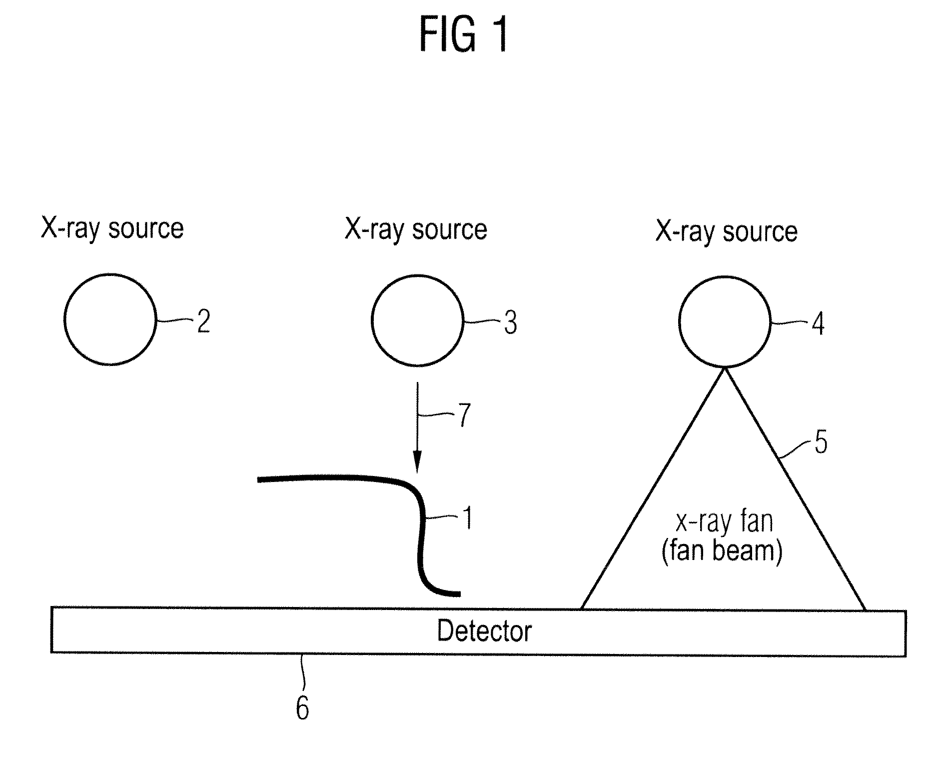
[0031]A segment of an object 1 that is to be tested is shown in FIG. 1. It is thereby a metal component, for example, that should be used in a vehicle. This is moved in the z-direction, i.e. into the plane of the drawing (by means of a conveyor belt that is not drawn, for example) and thereby exposed with test radiation. In the conventional system shown in FIG. 1, three conventional x-ray sources 2 through 4 are used for the testing of objects. These x-ray sources 2 through 4 generate an x-ray beam 5 which is, for example, a fan beam. In x-ray acquisitions, x-ray radiation transmitted through the object 1 to be tested is received by a detector 6. In this manner, projections are thus obtained that allow conclusions about the material properties of the object 1.

[0032]Conventional x-ray tubes as used in FIG. 1 essentially include a vacuum chamber with housing in which a cathode and an anode are enclosed. The cathode thereby acts as a negative led that emits electrons to the positive an...


PUM


Abstract

In a device and a method for testing an object for material defects, a multi-emitter x-ray source, at least one x-ray detector and a control system to activate emitters of the multi-emitter x-ray source are thereby used. A selective activation of individual emitters or of a portion of the emitters is conducted according to the requirements of at least one item of information related to the tested object. The Flexible and low-cost materials testing is achieved.

Description

BACKGROUND OF THE INVENTION[0001]1. Field of the Invention[0002]The present invention concerns a device and a method to examine an object for material defects by means of x-rays.[0003]2. Description of the Prior Art[0004]X-ray testing methods are used in non-destructive substance and material testing in industrial manufacturing. A variety of components (that includes motors, robot components, vehicle parts and many others) can be tested. In non-destructive x-ray examination, the sample pieces or test subjects are typically introduced into a housing that is externally shielded from x-ray radiation and there are exposed with x-rays inside the housing. Inclusions or cavities, material defects, internal fractures and tears that are not visible from the outside can then be analyzed by means of x-rays.[0005]Conventional x-ray exposures of objects provide a two-dimensional projection of the objects, which allows a determination of the attenuation or absorption of the x-ray radiation upon p...

Claims


Application Information

Patent Timeline
IPC IPC(8): G01B15/06
CPCG01N23/046H01J35/04H01J35/065G01N2223/419H01J2235/062H01J2235/068H01J2235/02
Inventor FUERST, JENSGOLDAMMER, MATTHIASKOWARSCHIK, MARKUSSTEPHAN, JUERGEN
Owner SIEMENS AG
Why Eureka
Try Eureka