Facet Joint Implant and Related Methods
a facet joint and implant technology, applied in the field of facet joint implants, can solve the problems of further vertebral slippage and/or eventual mechanical lower back pain, and achieve the effects of preserving the natural motion of the spine, preserving the foraminal space, and avoiding mechanical pain
- Summary
- Abstract
- Description
- Claims
- Application Information
AI Technical Summary
Benefits of technology
Problems solved by technology
Method used
Image

Examples
first embodiment
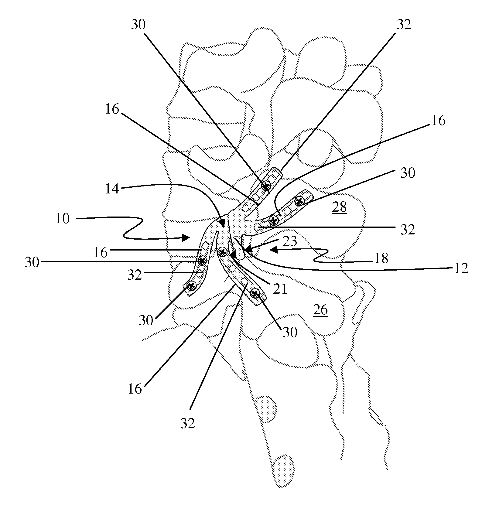
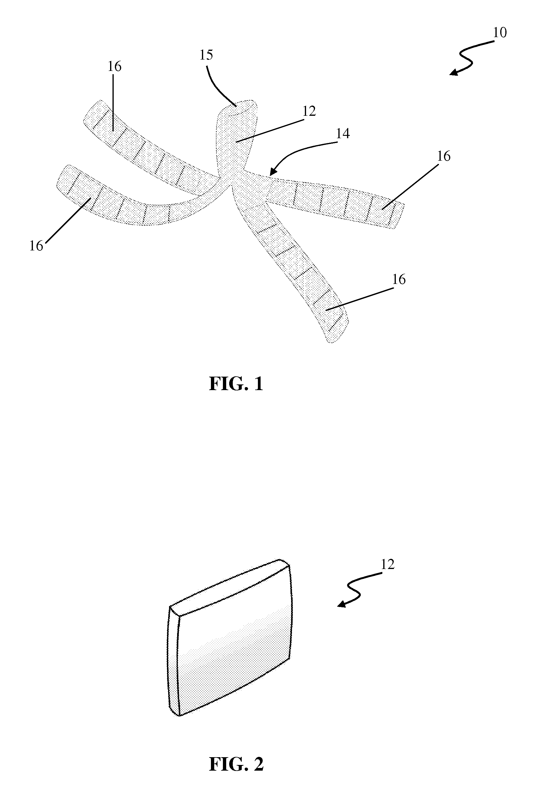
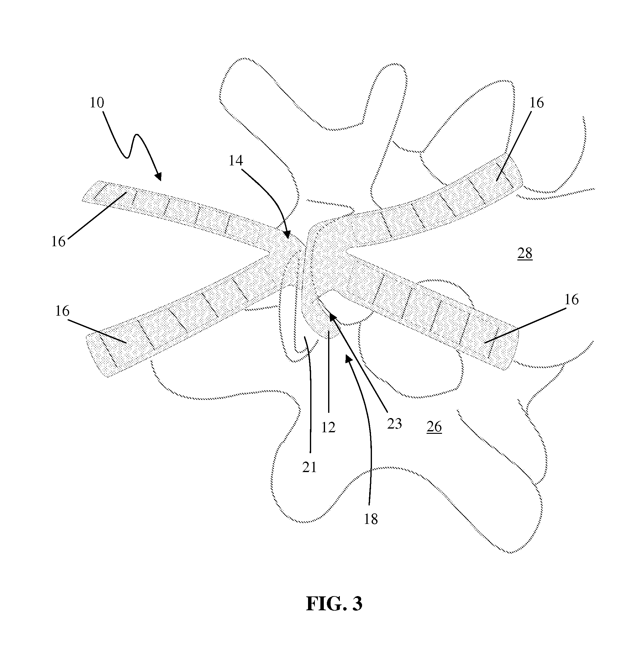
[0133]FIGS. 1-9 illustrate an example of a facet implant 10 according to the present invention. Implant 10 includes a spacer 12 (shown by itself in FIG. 2) disposed within an encapsulating jacket 14 having a plurality of attachment flanges 16. In the example shown in FIG. 1, the jacket 14 includes a body portion 15 that at least partially surrounds the spacer 12. The attachment flanges 16 extend from one end of the body portion 15 such that upon insertion within a facet joint, the flanges 16 will all extend outside the joint in a similar manner. To repair / reconstruct a facet joint 18, the implant 10 is positioned between a superior articular facet 21 (of an inferior vertebra 26) and an inferior articular facet 23 (of a superior vertebra 28) to prevent bone-on-bone contact, as shown in FIG. 3.
[0134]Once the spacer 12 is implanted between the articular facets 21, 23 of the facet joint 18, attachment flanges 16 secure the implant 10 in situ, as shown in FIGS. 5 & 8. The attachment flan...
second embodiment
[0137]Although described above as having an encapsulating jacket 14, the facet implant of the present invention may be provided without an encapsulating jacket. For example, FIGS. 10 & 11 illustrate an example of a facet implant 10a according to the present invention. The implant 10a comprises a spacer 12 with attachment flanges 16 that are directly connected to the spacer 12 (instead of being connected to an encapsulating jacket). In this embodiment, the spacer 12 may also have a centrally located attachment flange 40. A bore 42 is drilled completely through the superior articular process 20 of the inferior vertebra 26. The centrally located attachment flange 40 on the spacer 12 passes through the bore 42 in the superior articular process 20 of the inferior vertebra 26 and is then secured into position on the outer surface of the articular process by a screw 30 or any other fixation element (e.g. nails, staples, sutures, buttons, anchors, etc.). The attachment flanges 16 may then b...
third embodiment
[0142]FIGS. 16-20 collectively illustrate an example of a facet implant 10b according to the present invention. According to this embodiment, the implant 10b comprises a spacer 12 with directly attached tie cords 116. Tie cords 116 are preferably attached to and / or protrude from approximately the middle of one side of the spacer 12. At least one bore 42 is drilled completely through the superior articular process 20 of the inferior vertebra 26. The spacer 12 is inserted in the facet joint 18 and the tie cords 116 are manipulated to pass through the bore 42 in the superior articular process 20. The tie cords 116 are then secured on the outer surface of the articular process 20. In the example shown, the tie cords 116 are secured to the outer surface of the articular process 20 using a button 130. Button 130 includes a pair of centrally positioned apertures 132 extending therethrough, the apertures 132 dimensioned to allow passage of the tie cords 116. The tie cords 116 may then be ti...
PUM
 Abstract
Description
Claims
Application Information