Apparatus and Method for Setting Mechanical Lash in a Valve-Deactivating Hydraulic Lash Adjuster

a technology of hydraulic lash adjuster and mechanical lash, which is applied in the direction of mechanical apparatus, valve arrangement, machines/engines, etc., can solve the problems of difficult and complicated setting of lash in this fashion, adversely affecting the opening and/or closing timing of the associated valve, and wear of the dhla during engine operation

Inactive Publication Date: 2011-03-17
DELPHI TECH IP LTD
View PDF99 Cites 16 Cited by
  • Summary
  • Abstract
  • Description
  • Claims
  • Application Information

AI Technical Summary

Benefits of technology

[0008]Briefly described, a DHLA in accordance with the present invention comprises a conventional hydraulic lash adjustment mechanism within a plunger slidably disposed within a pin housing that is slidably disposed within an axial bore in an adjuster body. A transverse bore in the pin housing contains two opposed, selectively-retractable locking pins that engage a lower annular groove including a locking surface in the adjuster body whereby the lash adjuster body and the pin housing are locked together for mutual actuation by rotary motion of the cam lobe to produce reciprocal motion of an engine RFF pivotably disposed on a domed head of the plunger.
[0009]A lash ring disposed in an annular groove near the outer end of the DHLA body includes a first portion extending into the bore in th

Problems solved by technology

Excess clearance or internal mechanical lash results in clatter and wear of the DHLA during engine operation.
Variations in internal mechanical lash can also adversely affect the opening and/or closing timing of the associated valve.
Setting the lash in this fashion is difficu

Method used


Image

  • Apparatus and Method for Setting Mechanical Lash in a Valve-Deactivating Hydraulic Lash Adjuster
  • Apparatus and Method for Setting Mechanical Lash in a Valve-Deactivating Hydraulic Lash Adjuster
  • Apparatus and Method for Setting Mechanical Lash in a Valve-Deactivating Hydraulic Lash Adjuster

Examples


Embodiment Construction

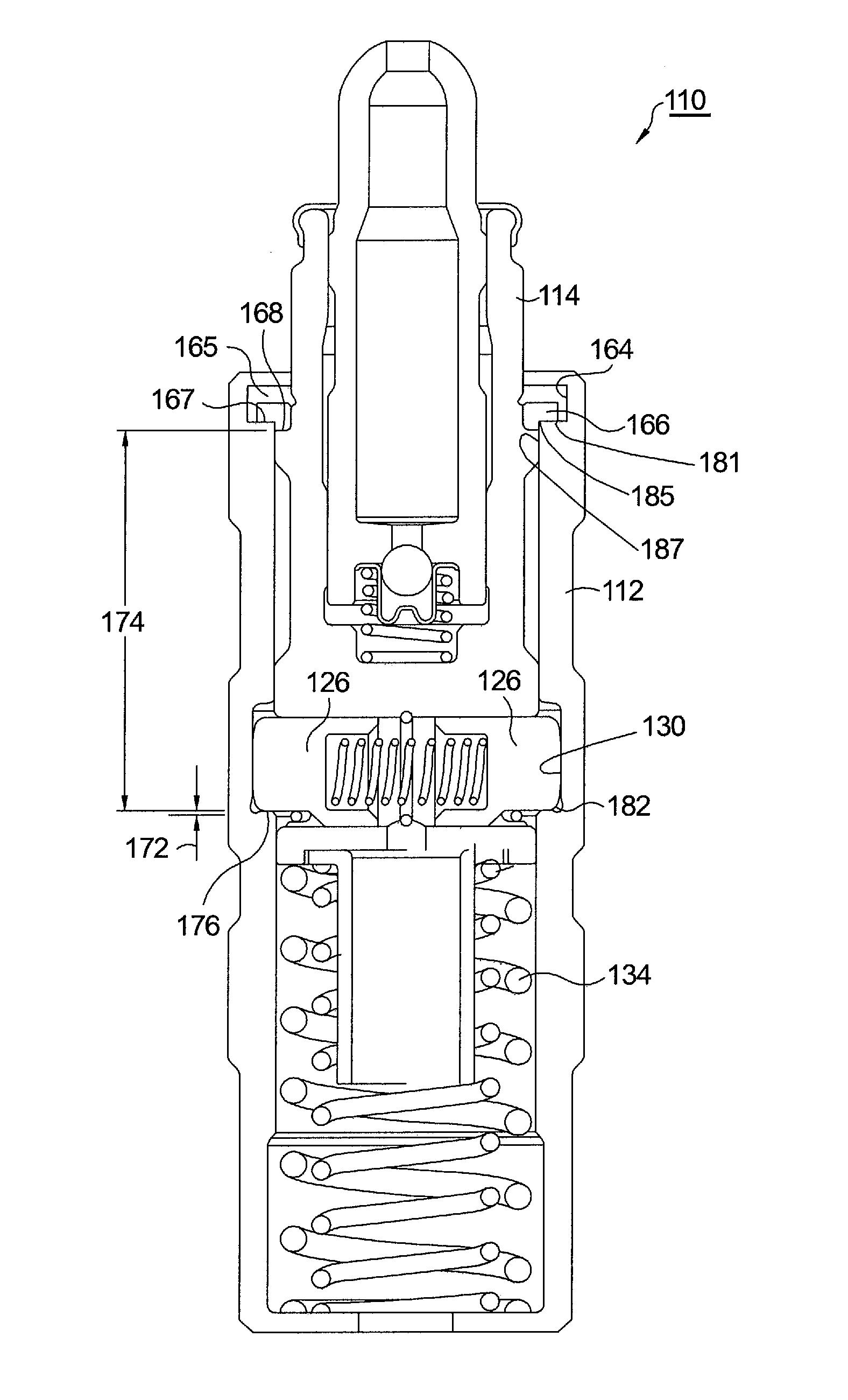
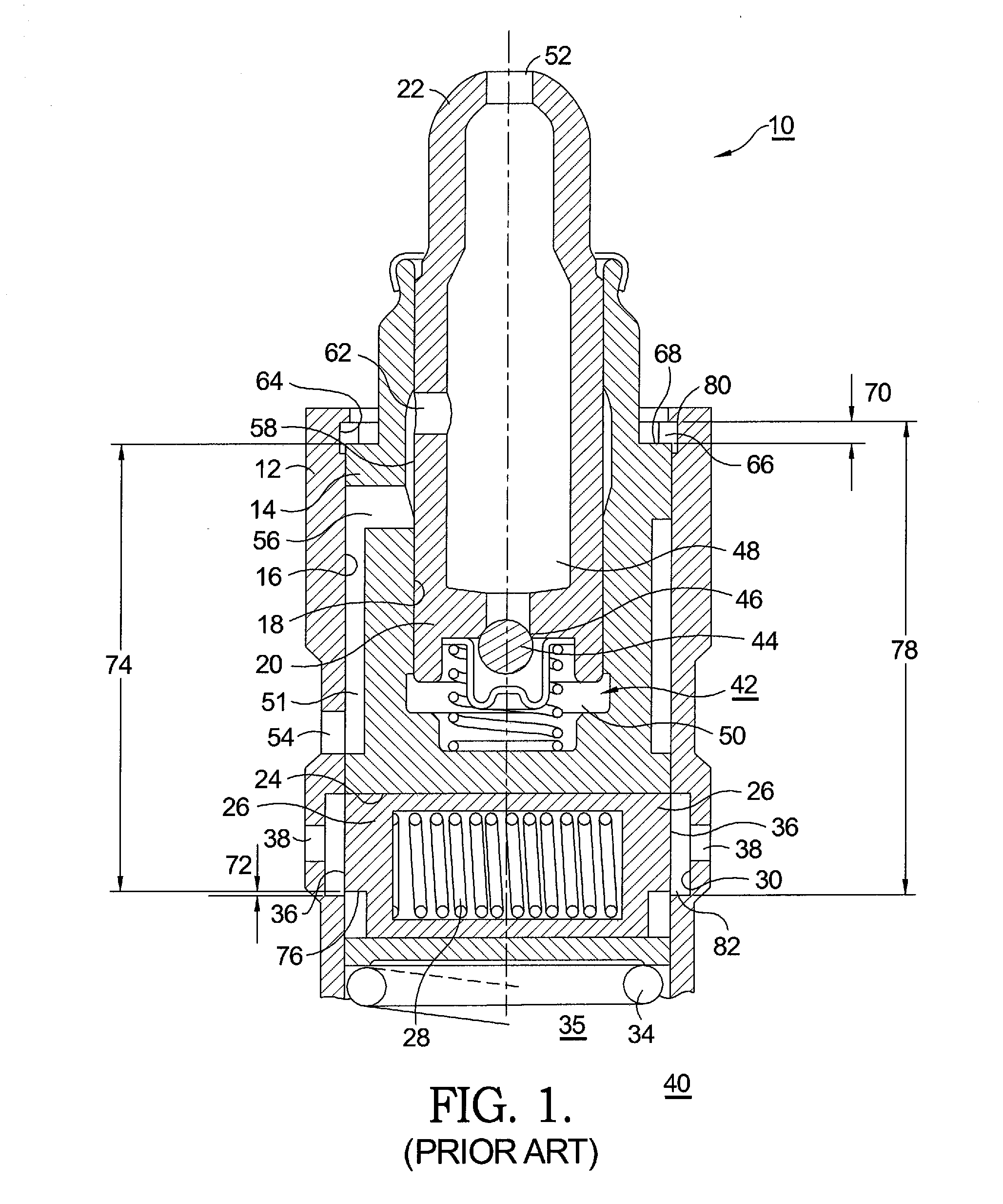
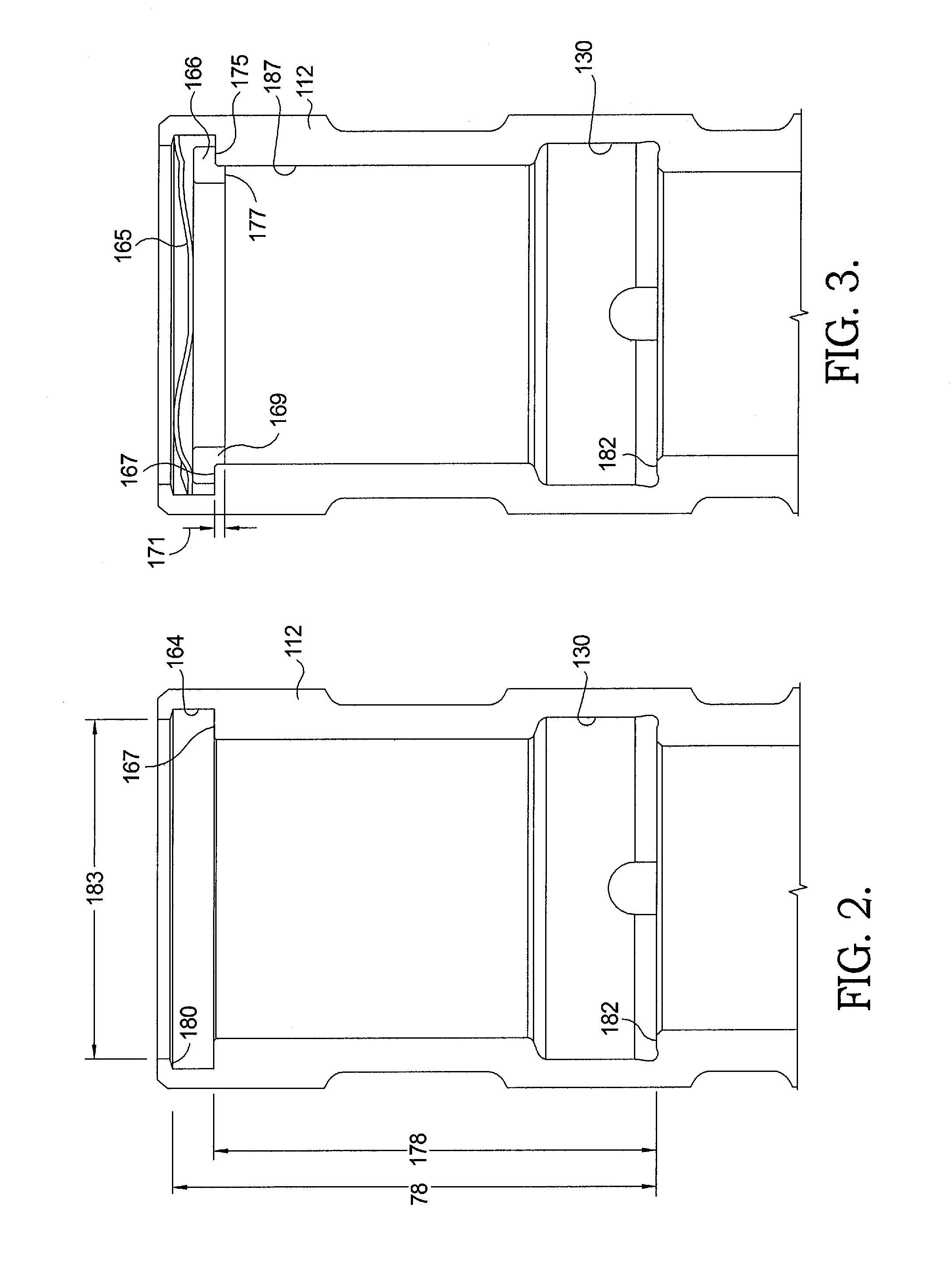
[0020]Referring to FIG. 1, a prior art DHLA 10 has a generally cylindrical adjuster body 12. A pin housing 14 is slidably disposed within a first axial bore 16 in adjuster body 12. Pin housing 14 itself has a second axial bore 18 for slidably receiving a plunger 20 having a domed end 22 for receiving a socket end (not shown) of a roller finger follower (not shown) in an overhead-cam engine valve train (not shown). Pin housing 14 has a transverse bore 24 slidably receivable of two opposed locking pins 26 separated by a pin-locking spring 28 disposed in compression therebetween. First axial bore 16 in is adjuster body 12 is provided with an annular groove 30 for receiving the outer ends of locking pins 26, thrust outwards by spring 28 when pins 26 are axially aligned with groove 30. In such configuration, DHLA 10 is in valve-activation mode. (As shown in FIG. 1, DHLA 10 is in valve-deactivation mode.) A loss-of-motion (LM) return spring 34 is disposed within a chamber 35 below pin hou...


PUM


Abstract

A DHLA including a hydraulic lash adjustment mechanism disposed within a plunger slidably disposed within a pin housing that is slidably disposed within an axial bore in an adjuster body. A lash ring disposed in a groove near the outer end of the DHLA body includes a portion extending into the bore to limit travel of the pin housing and thereby set the internal mechanical lash in the DHLA. The lash ring has a thickness selected to provided a predetermined amount of mechanical lash in the assembled lifter, which thickness varies from assembly to assembly to compensate for manufacturing variation in the components. A biasing means such as a wave ring, a Belleville washer or a beveled retaining ring is also installed in the annular groove to urge the lash ring against the lower surface of the groove under all DHLA operating conditions.

Description

TECHNICAL FIELD[0001]The present invention relates to valve train members such as hydraulic lash adjusters (HLAs) for supporting roller finger followers in overhead-camshaft valvetrains in internal combustion engines; more particularly, to such HLAs having means for selectively engaging and disengaging activation of valves in valvetrains; and most particularly, to apparatus and method for setting internal mechanical lash in a deactivating hydraulic lash adjuster (DHLA).BACKGROUND OF THE INVENTION[0002]It is well known that overall fuel efficiency in a multiple-cylinder internal combustion engine can be increased by selective deactivation of one or more of the engine valves, under certain engine load conditions. For example, for an overhead-cam engine, a known approach to providing selective deactivation is to equip a valvetrain member such as the hydraulic lash adjusters for the overhead-cam engine valvetrains with means whereby the roller finger followers (RFFs) may be rendered inc...

Claims


Application Information

Patent Timeline
IPC IPC(8): F01L1/34F01L1/20
CPCF01L1/24F01L13/0005F01L1/2405
Inventor HENDRIKSMA, NICK J.
Owner DELPHI TECH IP LTD
Why Eureka
Try Eureka