Control valve

a technology of control valve and valve body, which is applied in the direction of valve operating means/releasing devices, mechanical equipment, transportation and packaging, etc., can solve the problems of delayed response during operation and difficulty in properly controlling the working fluid

Active Publication Date: 2011-03-17
EAGLE INDS
View PDF7 Cites 13 Cited by
  • Summary
  • Abstract
  • Description
  • Claims
  • Application Information

AI Technical Summary

Benefits of technology

[0023]According to thus-constituted control valve, the fuselage portion where the first valve portion and the second valve portion of the valve body are connected is formed with a flow passage between the valve bore surface and itself, so that the fluid flowing in the fuselage portion allows stabilizing the fuselage portion to hold it at an axis of the valve bore surface. Therefore, without any guiding component to the valve body, the first valve portion surface can reliably be jointed with t...

Problems solved by technology

Therefore, the first valve body 120 pressed by the first spring 140A in which the force changes depending on the displaced position may cause delayed response during the operation....

Method used


Image

  • Control valve
  • Control valve
  • Control valve

Examples


first embodiment

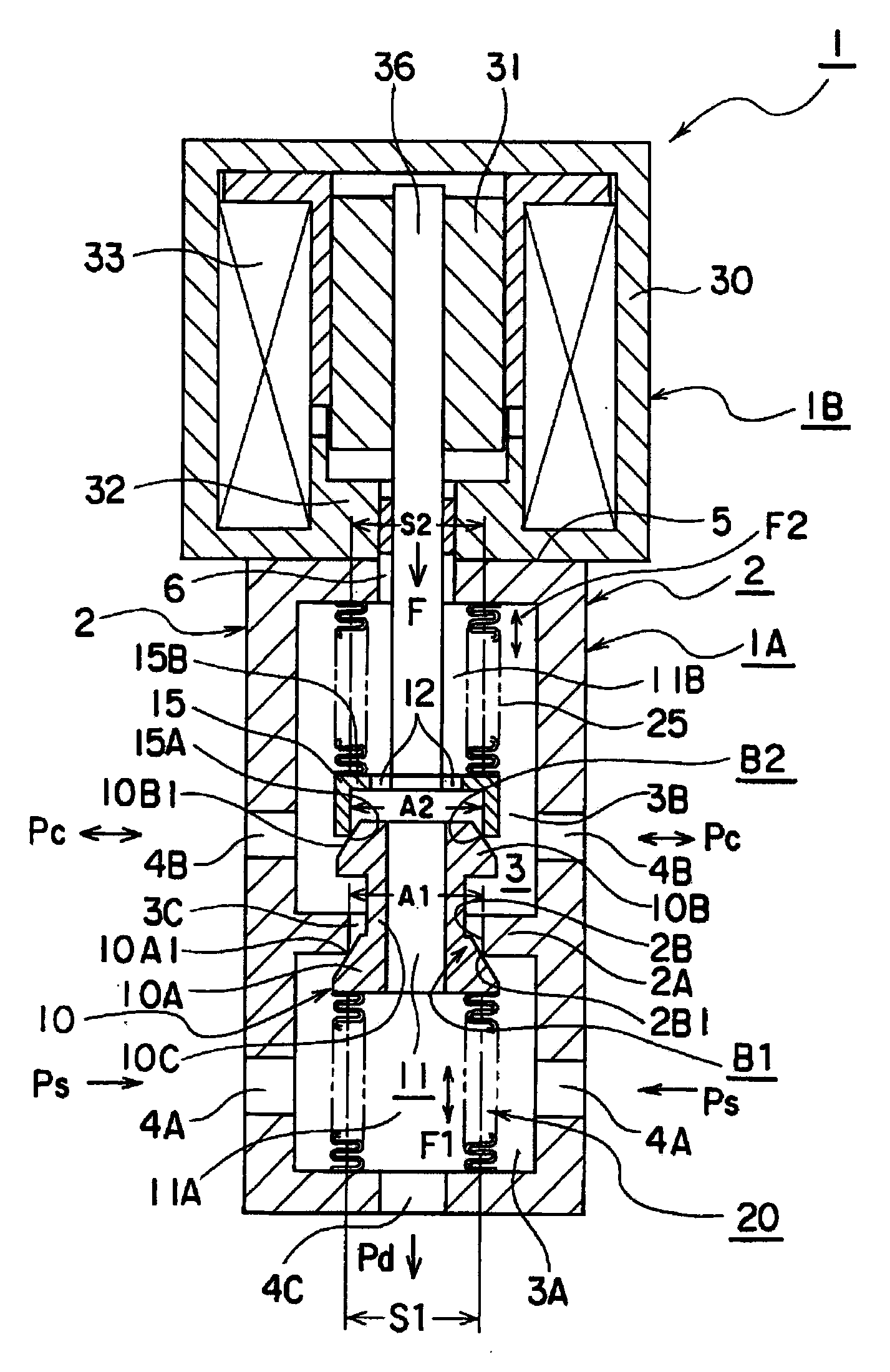
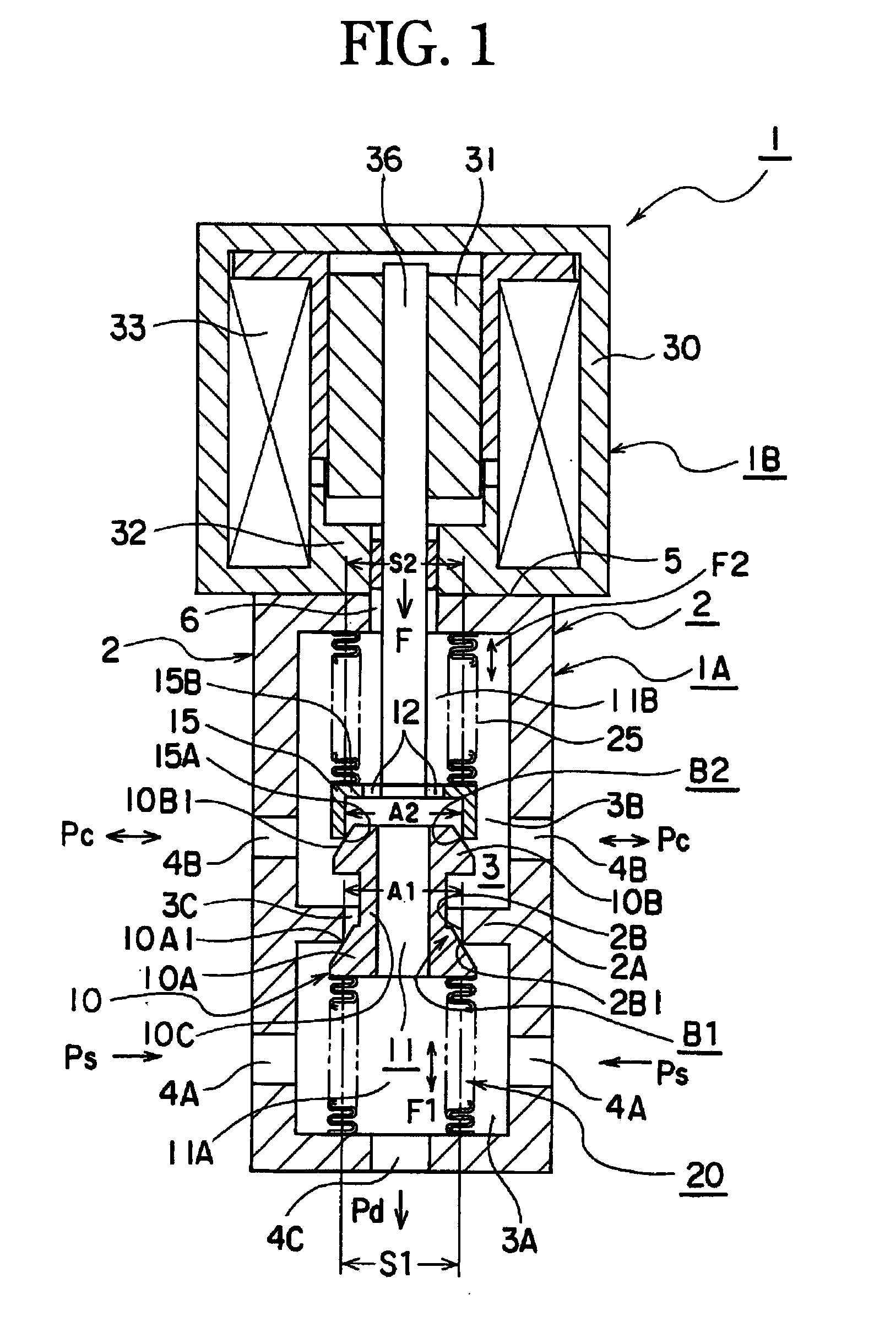
[0034]FIG. 1 is a sectional view of a control valve 1 showing a first embodiment according to the present invention. In FIG. 1, the control valve 1 controls a capacity (a ratio of valve opening). The control valve 1 is integrally formed by uniting a control valve portion 1A and a solenoid portion 1B. An outer frame of the control valve portion 1A is a main body 2. The inside of the main body 2 is provided with a valve space chamber 3 having an axially-long shape. The valve space chamber 3 is divided by a partition portion 2A to form a first valve chamber 3A at one side of the partition portion 2A and a second valve chamber 3B at the other side. Further, the partition portion 2A is provided with a valve bore surface 2B in the surrounding surface of a through-hole penetrating the first valve chamber 3A and second valve chamber 3B at its axis. Also, a first valve seating surface 2B1 is formed in an end portion at the side of the first valve chamber 3A in the valve bore surface 2B. The ...

second embodiment

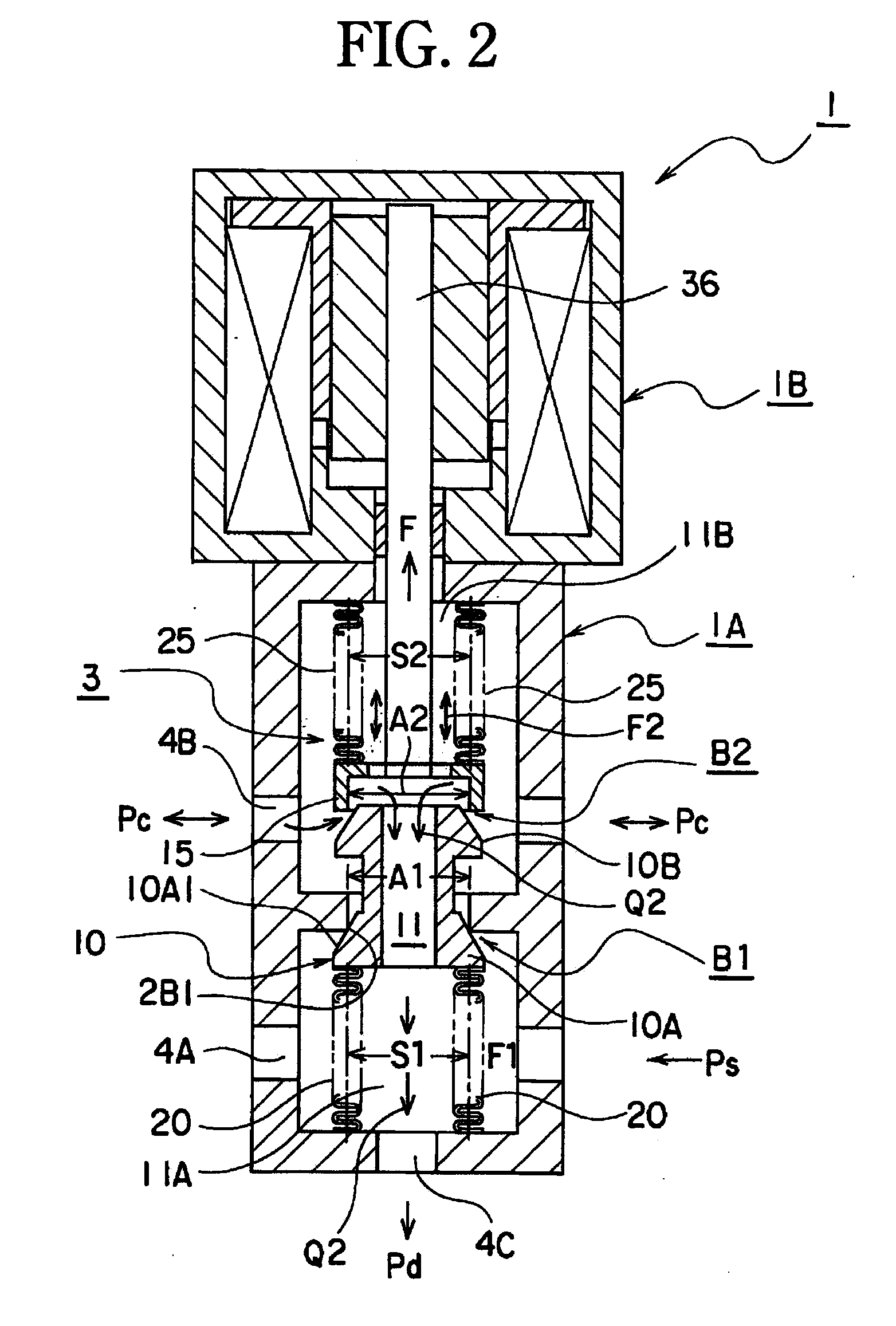
[0062]Next, FIG. 4 is a sectional view showing a part of a solenoid portion 1B of a control valve 1 of a second embodiment according to the present invention. Also, FIG. 5 is a magnified view around the valve body 10 of FIG. 4. Further, FIG. 6 is a detailed sectional view of the partition portion 2A of FIG. 5. Further, FIG. 7 is a bottom view of the partition portion 2A shown in FIG. 6. The following description is based on FIG. 4, FIG. 5, FIG. 6 and FIG. 7. A solenoid portion 1B in the control valve 1 is not further explained since it has approximately same constitution as in FIG. 1. Also, a control valve portion 1A of FIG. 4 is modified in a part of components in FIG. 1, but has same constitution as in FIG. 1. Hereinafter, components different from the control valve 1 of FIG. 1 will be explained. As shown in FIG. 4, a third spring 22 is arranged in a second pressure-sensing device 25. The third spring 22 is not always required but is provided for ensuring the elastic-pressing to a...


PUM


Abstract

A control valve capable of performing capacity control independent of the pressure of operation fluid and according to preset conditions. The control valve opens and closes a first poppet valve and a second poppet valve by a solenoid section where a solenoid rod is moved according to the magnitude of an electric current. In the control device, the following pressure-receiving areas are set to be substantially equal to each other: the first effective pressure-receiving area of a first pressure-sensing spring device forming the first poppet valve and the second poppet valve, the second effective pressure-receiving area of a second pressure-sensing spring device, the first pressure-receiving area on the inner side of a portion where a first valve seat surface and a first valve section surface are in contact with each other, and the second pressure-receiving area on the inner side of a portion where a second valve seat surface and a second valve section surface are in contact with each other.

Description

TECHNICAL FIELD[0001]The present invention relates to a control valve used for capacity control of a fluid, e.g. capacity control of power transmission device, etc. Particularly, the present invention relates to a control valve, in which ineffective control due to unbalanced fluid pressure acting on a valve body or malfunction associated with sliding resistance at operation of the control valve, or delay in spring means, etc., due to fast moving of the valve body are improved for capacity control.BACKGROUND ART[0002]As a related art of the present invention, a control valve is known. This control valve is a constitution as shown in FIG. 8 (e.g. Japanese Unexamined Patent Publication No. 2004-197858 (Patent Document 1)). This pressure control valve is a three-way valve used for, for example, pressure control of a switching clutch provided in a line of control system, etc., in an automatic transmission, pressure control of a switching brake, and pressure control of a line.[0003]The co...

Claims


Application Information

Patent Timeline
IPC IPC(8): F16K31/12
CPCF16K31/0693F16K31/0655Y10T137/87217Y10T137/777Y10T137/86702Y10T137/87241
Inventor OKAMOTO, EIJI
Owner EAGLE INDS
Why Eureka
Try Eureka