Composite brake disc

Inactive Publication Date: 2011-03-17
RASSINI FRENOS S A DE
View PDF17 Cites 18 Cited by
  • Summary
  • Abstract
  • Description
  • Claims
  • Application Information

AI Technical Summary

Benefits of technology

[0025]The unique two-part design of the brake disc of the present invention enables design considerations, such as thinner wall sections, to be achieved, while simultaneously reducing mass. The specialized fabrication of the mounting portion creates localized areas of high dampening, thereby significantly reducing

Problems solved by technology

It has been recognized that heating of the brake plate portion during manufacture and use in a motor vehicle will cause various forms of warpage and deformation, particularly including radial deformation.
Th

Method used


Image

  • Composite brake disc
  • Composite brake disc
  • Composite brake disc

Examples


Embodiment Construction

[0035]The brake disc arrangement of the present invention is formed of essentially two parts. These are, as will be described in detail herein, a mounting portion and a brake plate portion. The manufacture of the mounting and brake plate portions will result in a brake disc wherein the mounting portion is physically constrained by the brake plate portion. Nevertheless, both such portions respond to external stimulus independently of each other. The result is a brake disc that is advantageously characterized by increased dampening, reduced deformation during service and manufacturing, and reduced mass.

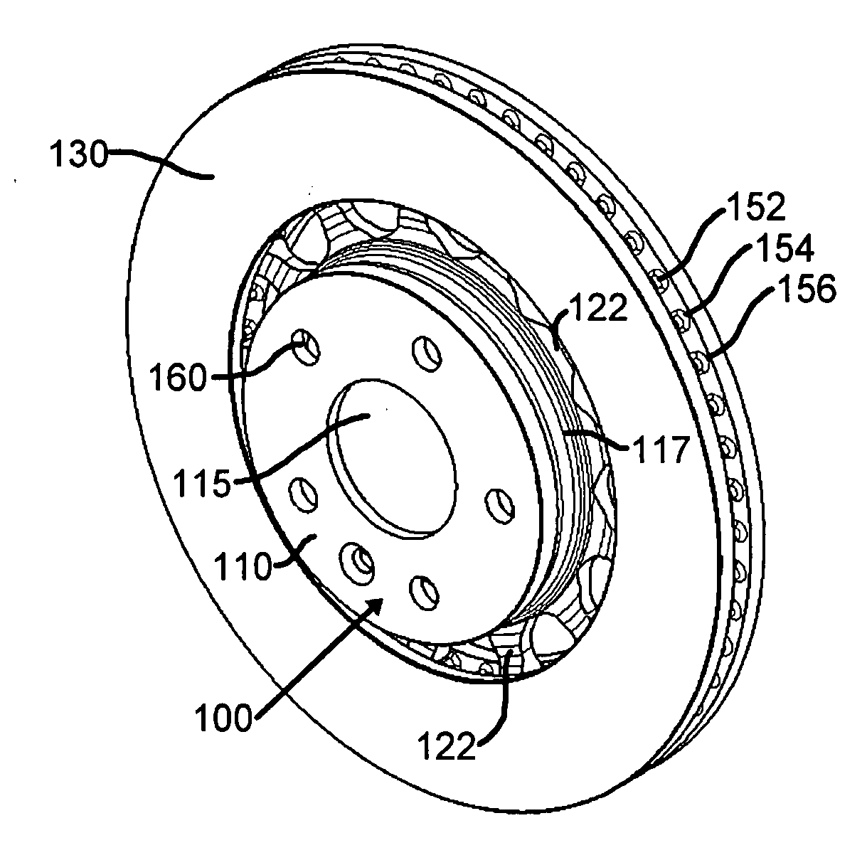
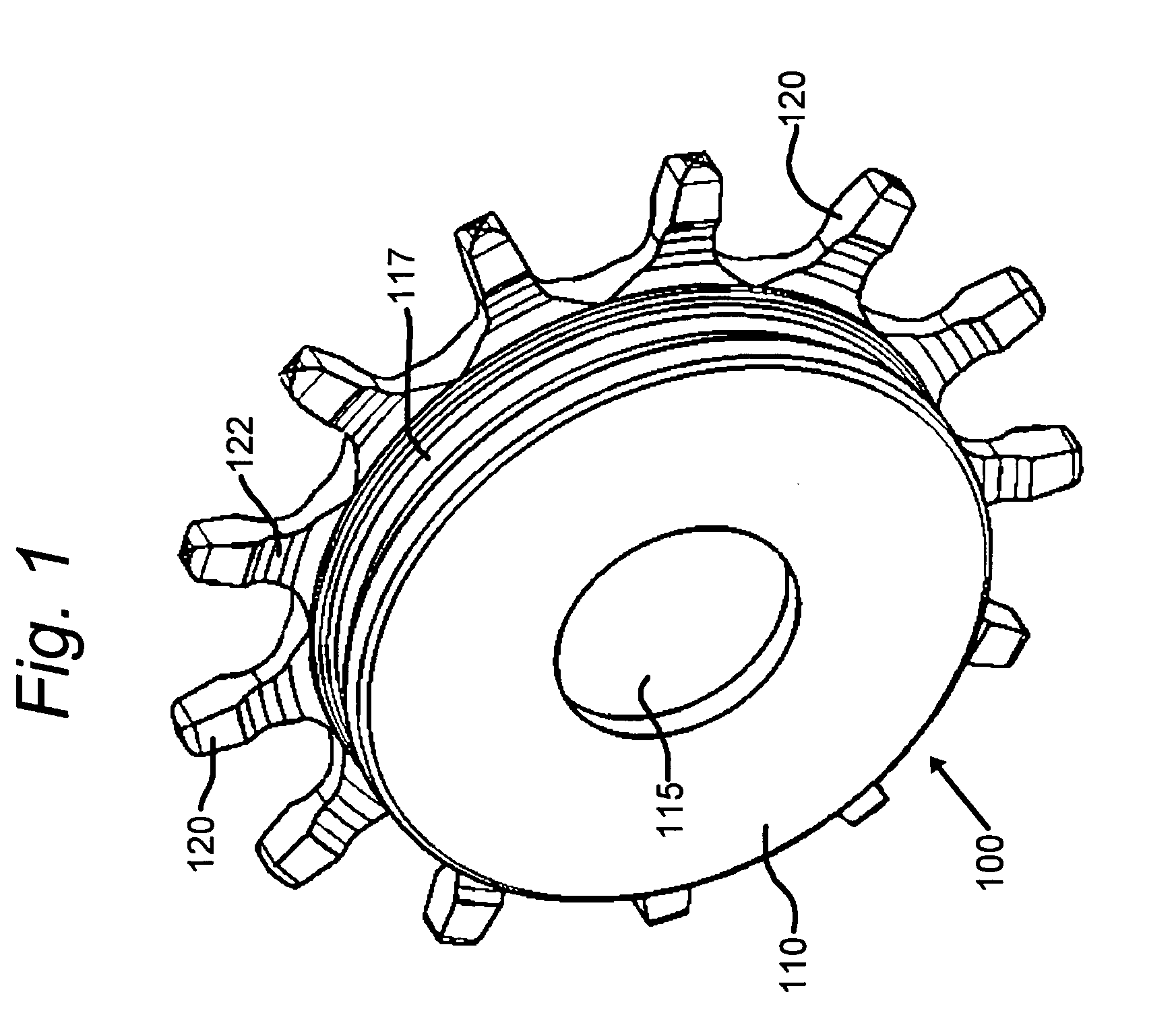
[0036]FIG. 1 is a simplified schematic perspective representation of a cast mounting portion 100 for use in a brake disc arrangement (not shown in this figure) in accordance with the invention. As will be described hereinbelow, mounting portion 100 supports and constrains the brake plate portion (not shown in this figure) through several radial protuberances 122 that are distributed sub...


PUM

PropertyMeasurementUnit
Microstructureaaaaaaaaaa

Abstract

A brake disc arrangement has a mounting portion formed of a metal, with a plurality of radial protuberances extending radially outward therefrom. The radial protuberances each have a radially distal tip portion, and a ceramic coating is applied to the radially distal tip portion of the radial protuberances. The brake plate portion is cast so as to surround the radially distal tip portions. However, it is isolated therefrom by the ceramic coating. At least some of the radially distal tip portions are formed of metal having a microstructure created by electrical discharge machining to increase dampening. A sand core within a core box holds the mounting portion in a predetermined fixed orientation. The molten metal is poured into the core box mold, and the metal brake plate portion is prevented by the ceramic coating from welding to any of the plurality of radial protuberances.

Description

RELATIONSHIP TO OTHER APPLICATION[0001]This application claims the benefit of the filing date of Provisional Patent Application Ser. No. 61 / 127,272, filed May 8, 2008. The disclosure of this provisional patent application is incorporated herein by reference.BACKGROUND OF THE INVENTION[0002]1. Field of the Invention[0003]This invention relates generally to brake discs for motor vehicles, and more particularly, to a composite brake disc arrangement formed of two cast portions, a mounting portion and a brake band portion, the two portions forming a frictional interface.[0004]2. Description of the Related Art[0005]Brake discs that conventionally are formed of a combination of a mounting portion and a brake plate portion employ, in some known arrangements, a continuous skirt extending radially outward of the mounting portion, the continuous skirt engaging a brake plate portion (i.e., brake band). The mounting portion is sometimes referred to as a “rotor hat,” due to its raised central po...

Claims


Application Information

Patent Timeline
IPC IPC(8): F16D65/12B22D19/00B22D25/02
CPCB22C9/10B22D19/0081B22D19/16F16D2250/0015F16D2065/1316F16D2065/1344F16D2065/136F16D65/12
Inventor ANDERSON, BRIAN KEITH-ROBERT
Owner RASSINI FRENOS S A DE
Why Eureka
Try Eureka