Portable charging apparatus

a charging apparatus and portability technology, applied in the direction of secondary cell charging/discharging, electric vehicles, lighting and heating apparatus, etc., can solve the problems of requiring a stock of spare batteries, requiring recharging of batteries in such lights, time-consuming, labor-intensive, etc., and achieve the effect of not easy to move and relatively easy to mov

Active Publication Date: 2011-03-17
GLOBAL DESIGN SOLUTIONS
View PDF15 Cites 19 Cited by
  • Summary
  • Abstract
  • Description
  • Claims
  • Application Information

AI Technical Summary

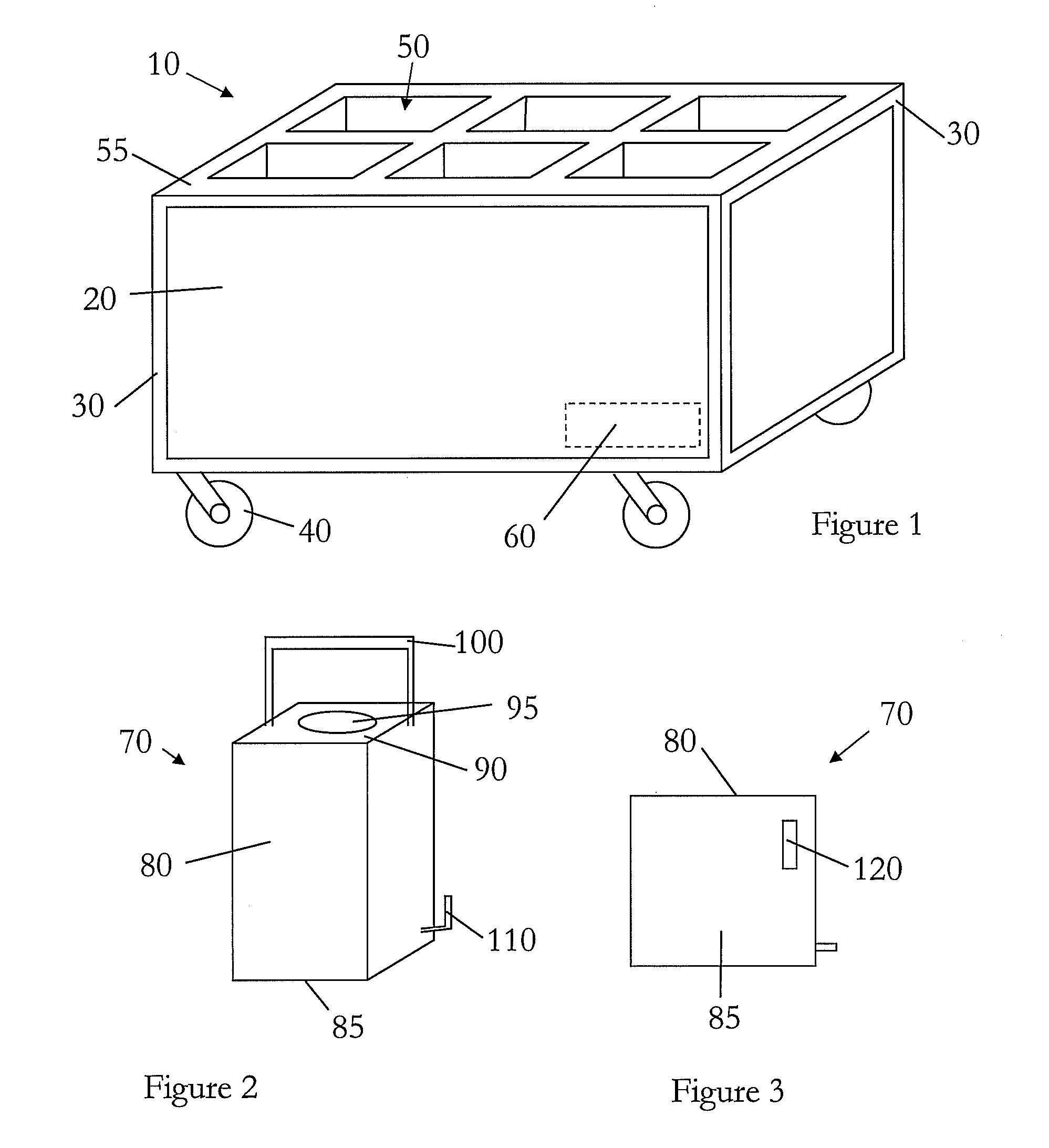
Benefits of technology

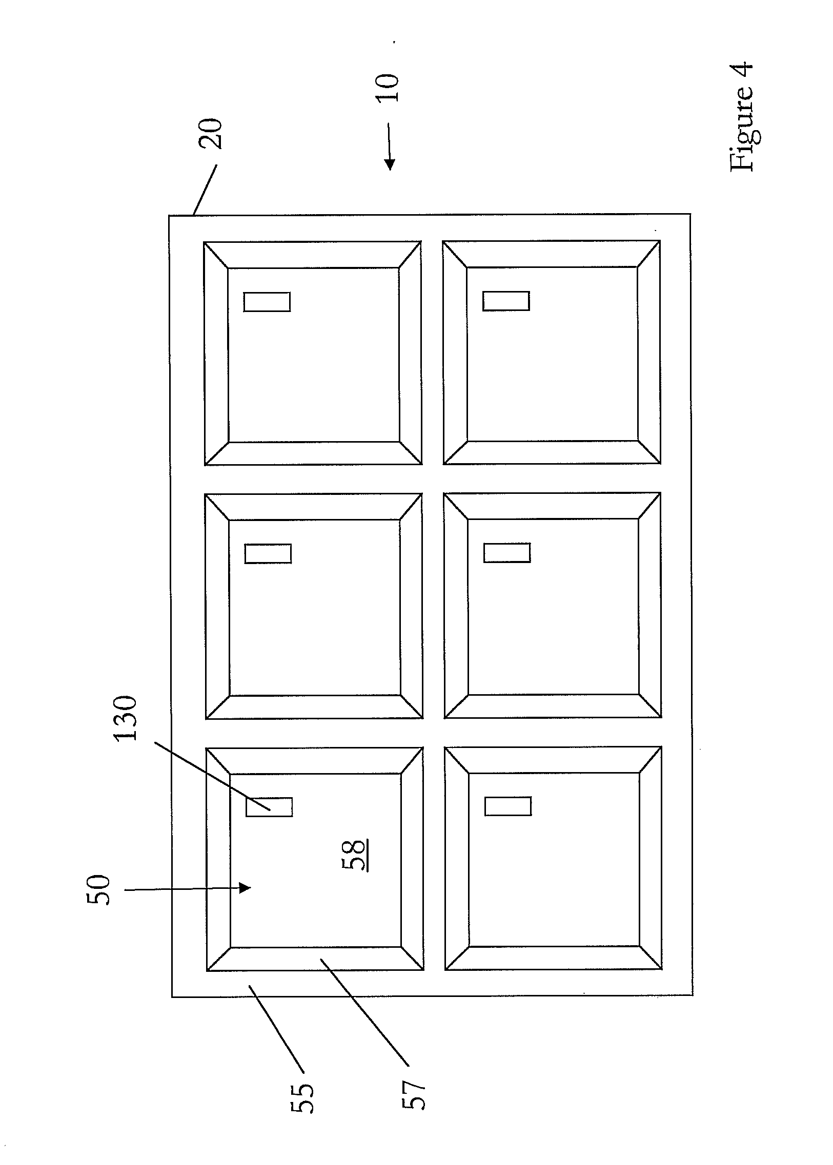
[0010]The term “portable” is used herein to mean that the apparatus may be moved from one location to another relatively easily, and excludes permanent and semi-permanent installations. The term “removable” means the units may be removed from the charging apparatus when required to be used as light units.
[0011]The container itself may be reinforced in that it is substantially robust, comprising materials substantially not susceptible to damage by moisture, and / or shock, and / or unexpected collision. The reinforcing may be comprised at least around the edges and / or corners of the container. In one embodiment, the container is a flight case. The container may include wheels and / or skids on its base to enable it to be moved relatively easily.
[0012]The receiving means may include impact absorbent material such as foam, polystyrene, or plastics. This material may be formed into sockets for receiving the light units such that the units cannot move easily within their individual socket. The material may be arranged around the sides, and / or the base, and / or the top of the light units. The container may include impact absorbent material to cover the top of the light units when in place within the receiving means. The sockets may be shaped to accommodate the light units in / with a close fit. This impact absorbent material could be described as shock-resistant material and is for protecting the light units from damage due to impacts, and the like, during storage within the apparatus.
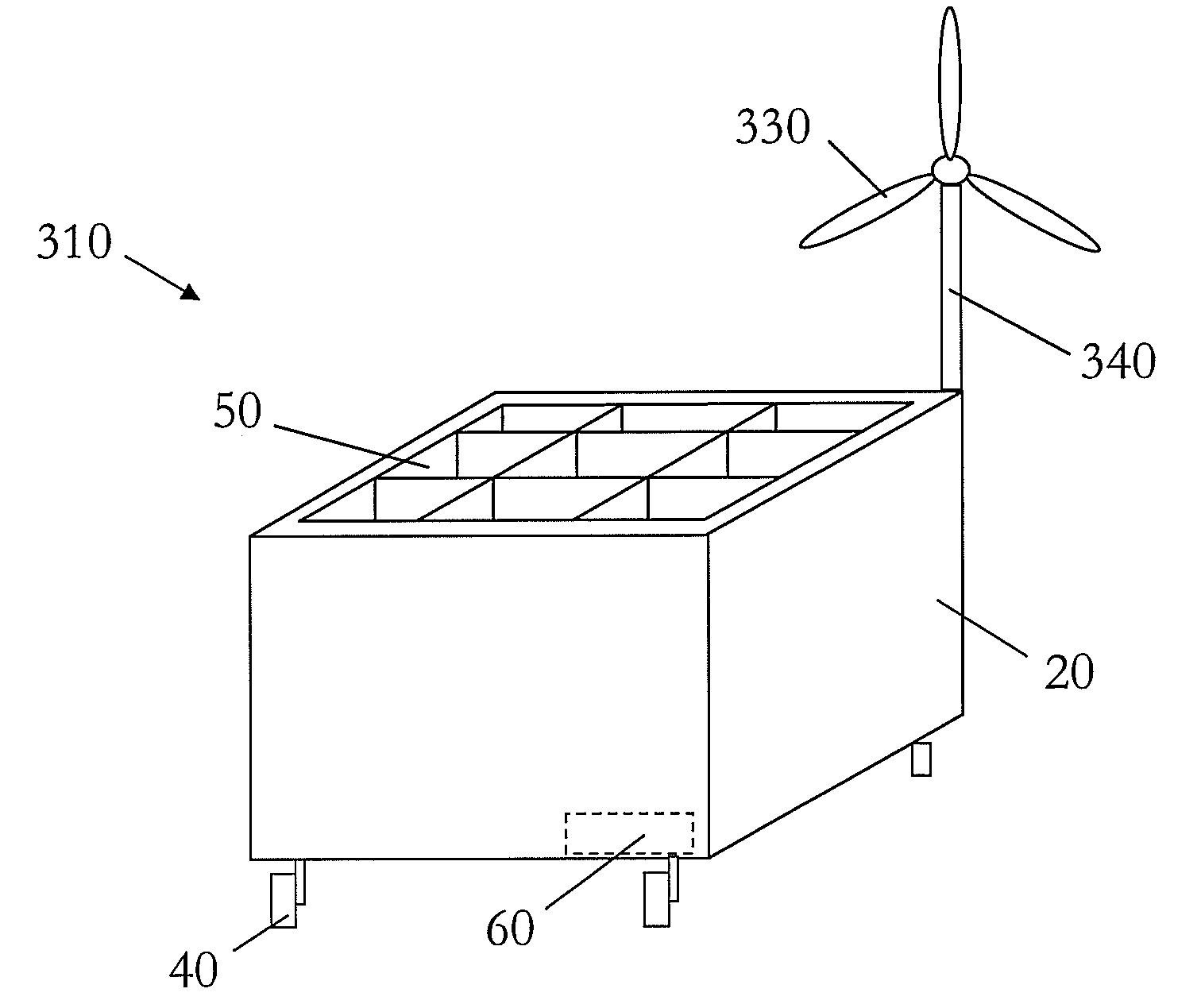
[0017]The apparatus may be connected to a supply of electricity such as the main supply in a building, or from a gasoline / petrol / diesel generator. This electricity supply may be provided at approximately 220 volts or 110 volts. However, it is also possible that the apparatus includes its own electricity generating means. This could be a gasoline / petrol or diesel generator. Alternatively, it could be a means for generating electricity from renewable energy such as a wind turbine or solar panel. The ability to operate the apparatus, without the need for connection to a main supply of electricity, allows for a cableless system.
[0028]The apparatus may hold any number of light units; but, it is expected to be within the group of one, two, four, six, eight or ten. The apparatus provides a container which securely holds the light units during transport. The apparatus allows the batteries with each light unit to be charged without the need to remove the batteries from the units and without the need to remove the units from the container. When required, the light units may be removed by lifting out of the container and sited as desired. They can be operated remotely. When the battery in the light unit has discharged, or the light unit is no longer required, it may be inserted into the container for storage and / or recharging and / or transport. Accordingly, the invention provides a simple and easy system for the supply of portable light units for events such as theatres, film studios, stages and the like. Due to the possibility of an independent power supply, such as solar panels, the apparatus allows for the supply and charging of the light units at outdoor events where a power supply may be difficult or undesirable to provide.

Problems solved by technology

However, the batteries in such lights require recharging.
What is not appreciated by the prior art is that this is time consuming, laborious and requires a stock of spare batteries.

Method used


Image

  • Portable charging apparatus
  • Portable charging apparatus
  • Portable charging apparatus

Examples


Embodiment Construction

[0037]The present invention will be described with respect to particular embodiments and with reference to certain drawings but the invention is not limited thereto but only by the claims. The drawings described are only schematic and are non-limiting. In the drawings, the size of some of the elements may be exaggerated and not drawn to scale for illustrative purposes. The dimensions and the relative dimensions do not correspond to actual reductions to practice of the invention.

[0038]Furthermore, the terms first, second, third and the like in the description and in the claims, are used for distinguishing between similar elements and not necessarily for describing a sequence, either temporally, spatially, in ranking or in any other manner. It is to be understood that the terms so used are interchangeable under appropriate circumstances and that the embodiments of the invention described herein are capable of operation in other sequences than described or illustrated herein.

[0039]More...


PUM

PropertyMeasurementUnit
voltageaaaaaaaaaa
currentaaaaaaaaaa
timeaaaaaaaaaa

Abstract

A portable charging apparatus for electrically charging one or more portable battery operated light units, comprising a container having one or more receiving means for receiving one or more portable battery operated light units, electricity supply connection means for electrically connecting with the one or more portable battery operated light units, and electricity supply regulating means.

Description

CROSS REFERENCE TO RELATED APPLICATION[0001]This application is related to, and claims priority from, United Kingdom Patent Application Serial No. GB0915972.4, filed Sep. 11, 2009, the entire contents of which is incorporated herein by reference.FIGURE SELECTED FOR PUBLICATION[0002]FIG. 1BACKGROUND OF THE INVENTION[0003]1. Field of the Invention[0004]The present invention relates to a portable charging apparatus for electrically charging one or more portable, battery operated, light units. More specifically, the present invention relates to a combination of a portable charging apparatus and one or more portable battery operated light units; and, a method of charging a portable battery operated light unit.[0005]2. Description of the Related Art[0006]The related art involves portable, battery operated, light units which are used in the events and stage industry for providing lighting. Their great advantage is that they are battery operated and thus require no trailing cables. This all...

Claims


Application Information

Patent Timeline
Patent Type & Authority Applications(United States)
IPC IPC(8): H01M10/46H02J7/00
CPCH02J7/0044H02J7/0027Y02E10/76H02J7/0013H02J2310/22H02J7/0042F21L2/00F21L4/08H02J7/0045H02J7/35
Inventor LLOYD, MATTHEWCUTHBERT, RICHARD
Owner GLOBAL DESIGN SOLUTIONS
Why Eureka
Try Eureka