
Estimation of blood flow and hemodynamic parameters from a single chest-worn sensor, and other circuits, devices and processes

a technology of hemodynamic parameters and blood flow, which is applied in the direction of diagnostic recording/measuring, applications, catheters, etc., can solve the problems of cumbersome equipment, unoptimized long-term and ambulatory monitoring, and inconvenient us

Inactive Publication Date: 2011-03-17
TEXAS INSTR INC
View PDF52 Cites 168 Cited by
  • Summary
  • Abstract
  • Description
  • Claims
  • Application Information

AI Technical Summary

Benefits of technology

The patent describes an electronic monitoring device that can isolate and filter out cardiac signals from other body monitoring signals. This allows for the accurate measurement of blood flow and other hemodynamic parameters. The device can also include an accelerometer sensor that delivers a signal that is free of heart pulses, making it easier to analyze. Overall, the invention improves the accuracy and reliability of monitoring living body signals.

Problems solved by technology

Most current solutions for heart rate monitoring involve cumbersome equipment, such as heart rate recording belts to be worn around the chest, electrocardiogram (ECG) electrodes and leads, and in most cases electrical contact to the skin.
However, such methods remain obtrusive, and are not optimal for long-term and ambulatory monitoring.
Current solutions for not only heart rate monitoring but also respiration monitoring are believed to involve cumbersome and expensive equipment e.g., respiration and heart rate monitoring belts to be worn around the chest, spirometers and canulas to be worn around the mouth and nose, and electrocardiogram (ECG) electrodes and leads to be taped on the body.
Not only are these solutions obtrusive and expensive, but may also be too restrictive to be well-suited for ambulatory monitoring.
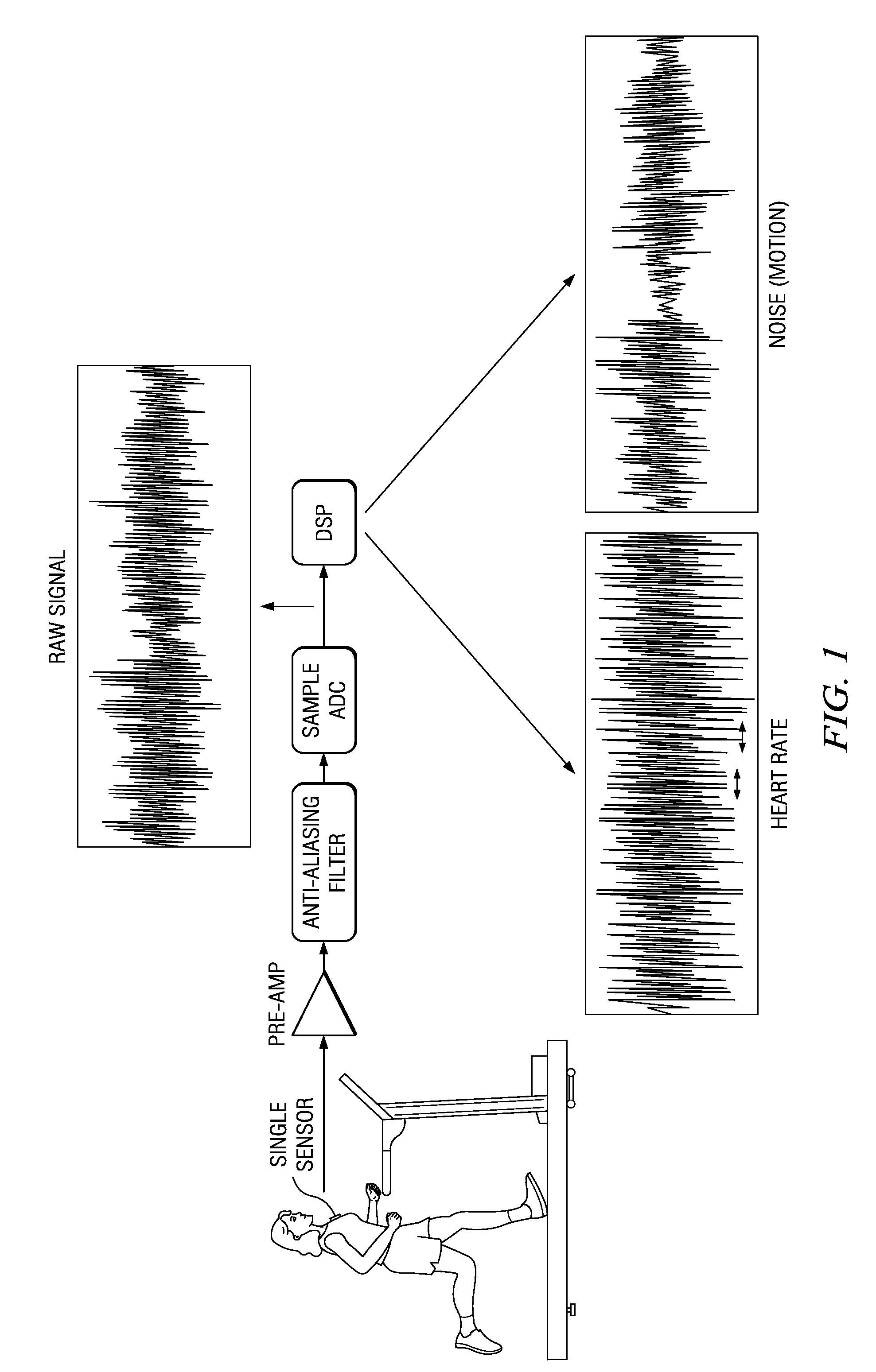
Noise mixed with signals received by the sensors used in heart monitoring, respiration monitoring, body motion and other monitoring applications can adversely affect the accuracy of each type of signal.
Such arrangements are very difficult to establish in a real setting and can cause poor rejection of the motion signal and body motion artifacts.
Some conventional single-channel de-noising techniques reinforce all major signal peaks and fail to distinguish body motions from heart sounds.
Hemodynamic data also challenge the art to find methods and devices for obtaining, isolating, determining and monitoring more simply, economically and more efficiently.
Most current solutions for the measurement of blood flow and other hemodynamic parameters are believed to involve cumbersome and expensive equipment e.g., Impedance Cardiography (calls for electrodes to be connected on the skin), Doppler Echo Cardiography, Continuous Blood Pressure Monitoring etc.
Not only are these solutions obtrusive and expensive, but may also be too restrictive to be well-suited for ambulatory monitoring applications.

Method used


Image

  • Estimation of blood flow and hemodynamic parameters from a single chest-worn sensor, and other circuits, devices and processes
  • Estimation of blood flow and hemodynamic parameters from a single chest-worn sensor, and other circuits, devices and processes
  • Estimation of blood flow and hemodynamic parameters from a single chest-worn sensor, and other circuits, devices and processes

Examples


embodiment 2

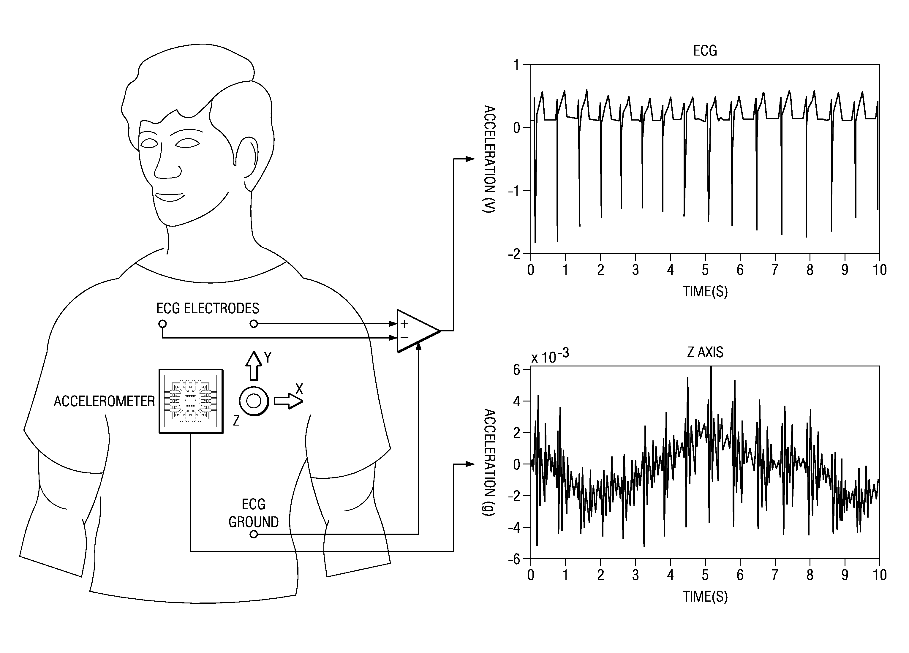
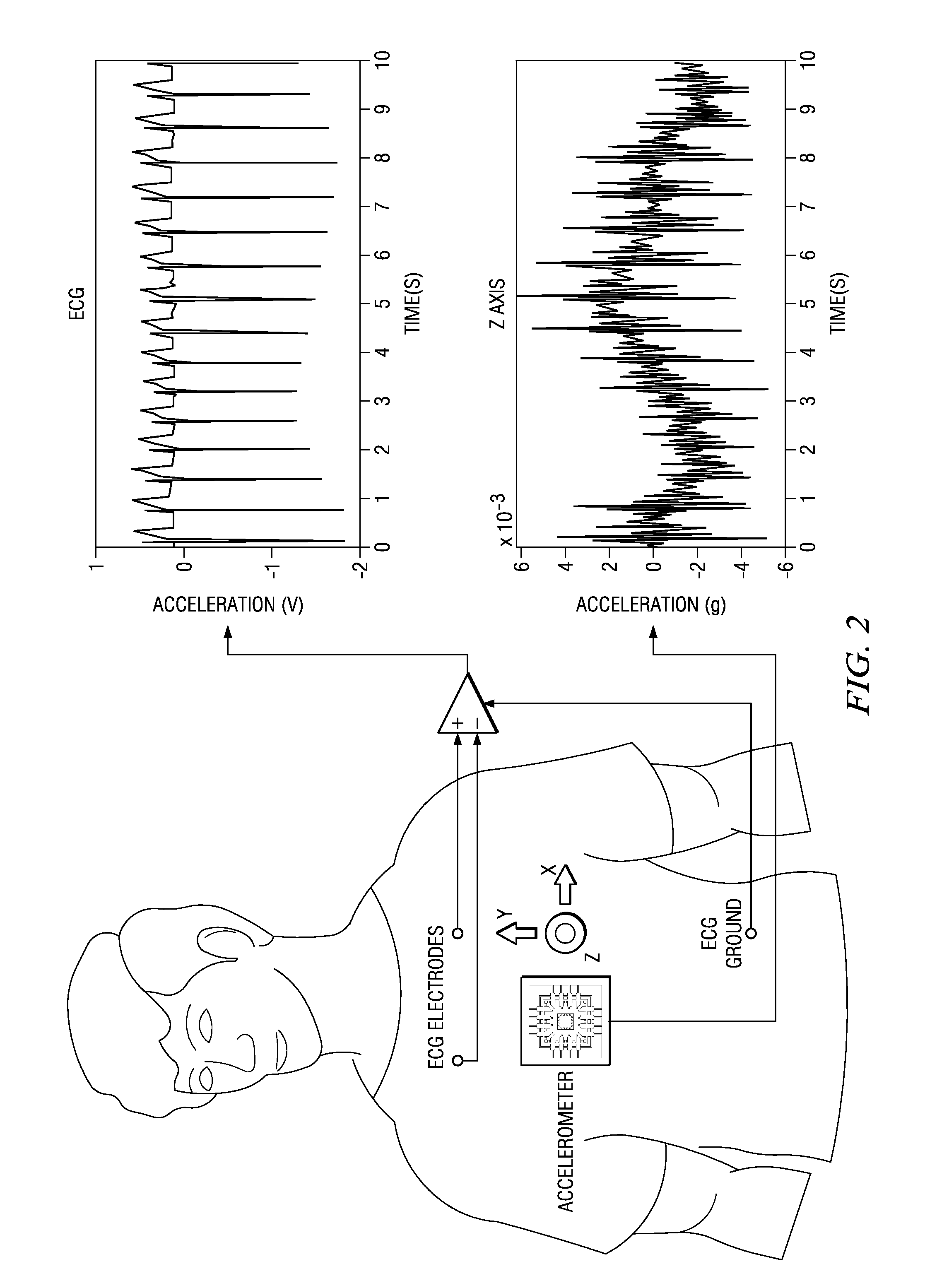
[0099]FIGS. 7A-7C show signal plots for an ECG filtering The plots have different time scales and walking conditions. Raw ECG signal from the ECG electrodes in FIG. 2 and a concurrent filtered ECG signal waveform, by applying steps 110-140 separately to the ECG signal, are depicted for a subject walking on a treadmill.

[0100]In another embodiment, satisfactory S1-S2 heart signals were extracted from raw motion-affected accelerometer Z-axis data by LPF (low pass filtering) with corner at 100 Hz and then Savitzky-Golay filtering at 20th order, followed by subtraction of the S-G signal from the LPF signal, and followed further by signal enhancement. It appears that polynomial filtering of motion-affected LPF accelerometer signals, using polynomial filtering on the order in a range of approximately 20th order or higher order to at least over 30th order, is satisfactory for obtaining heart signals as a residue by subtraction of the polynomial filtering output from the LPF signals. Using ...

embodiment 600

[0173]FIG. 24 shows an implementation of a wired system embodiment 600 for a respiration and cardiac monitoring system. An accelerometer 510 is strapped to the chest of the person being monitored. An axis sensor signal is coupled to a data acquisition signal processing unit 520 having a stream data interface and an associated data storage unit 530 for the signal stream and for instructions and parameters. The signal processing unit 530 supplies process monitoring data to one or more display units 550.i, each having a respective data storage unit 560.i. A first form of display 550.1 shows the heart sound signal and / or heart rate. A second form of display 550.2 shows the body motion signal. A third form of display 550.3 shows the respiration signal and / or respiration rate and / or or respiration depth (how deeply the person is breathing) and / or other respiration parameters. Various parameters for respiration are obtained from the respiration waveforms by finding various values on the wa...


PUM


Abstract

An electronic monitoring device includes an electronic processor (520) having at least one signal input for body monitoring, and a memory (530) holding instructions for the electronic processor coupled to the electronic processor so that the electronic processor is operable to isolate a cardiac signal including cardiac pulses combined with other cardiac signal variations, and the electronic processor further operable to execute a filter (730) that separates a varying blood flow signal from the cardiac pulses and to output information (790) based on at least the varying blood flow signal. Other devices, sensor assemblies, electronic circuit units, and processes are also disclosed.

Description

CROSS-REFERENCES TO RELATED APPLICATIONS[0001]This application is related to U.S. patent applications as follows:[0002]This application is related to U.S. patent application: “Heart Monitors And Processes With Accelerometer Motion Artifact Cancellation, And Other Electronic Systems” Ser. No. 12 / ______ (TI-68518) filed Aug. 24, 2010 simultaneously herewith, for which priority is claimed under 35 U.S.C. 120 and all other applicable law, and which is incorporated herein by reference in its entirety.[0003]This application is related to U.S. patent application “Motion / Activity, Heart-Rate And Respiration From A Single Chest-Worn Sensor, Circuits, Devices, Processes And Systems” Ser. No. 12 / ______ (TI-68552) filed Aug. 24, 2010 simultaneously herewith, for which priority is claimed under 35 U.S.C. 120 and all other applicable law, and which is incorporated herein by reference in its entirety.[0004]This application is related to provisional U.S. patent application “Motion Artifact Cancella...

Claims


Application Information

Patent Timeline
Patent Type & Authority Applications(United States)
IPC IPC(8): A61B5/0205A61B5/0402A61B5/026A61B5/029
CPCA61B5/029A61B5/0402A61B5/1102A61B2560/0475A61B7/008A61B2505/07A61B2562/0219A61B5/6831A61B5/113A61B5/7207A61B5/725A61B2562/028A61B5/7278A61B7/00A61B5/318A61B5/316
Inventor PANDIA, KEYA R.RAVINDRAN, SOURABHCOLE, EDWIN RANDOLPH
Owner TEXAS INSTR INC
Learn More