Tracking Fiber Optic Wafer Concentrator

a technology of fiber optic wafers and concentrators, which is applied in the field of concentrators, can solve the problems of reducing efficiency, reducing efficiency, and high associated manufacturing and maintenance costs, and requiring a great deal of maintenan

Inactive Publication Date: 2011-03-24
GENIE LENS TECH
View PDF50 Cites 38 Cited by
  • Summary
  • Abstract
  • Description
  • Claims
  • Application Information

AI Technical Summary

Benefits of technology

[0018]The inventors recognized the need for a new type of collector or “concentrator” that may be used for thermal power generation, in thermal PV systems, and concentrator PV systems. To this end, the inventors propose a concentrator for a solar energy system (e.g., a concentrated solar power (CSP) system) such as a scalable, linear Fresnel collector system or assembly that uses fiber optic wafers or pipes. The concentrator may be thought

Problems solved by technology

Most concentrators, such as parabolic trough concentrators, provide limited efficiencies, have high associated manufacturing and maintenance costs, and utilize mirrors rather than lenses to concentrate sunlight.
In the majority of these CSP systems, the collector or receiver (or absorber tube) is located in front of the mirrored surfaces of the reflector and causes shadowing, which leads to decreased efficiencies.
High quality mirrors or reflectors are also very expensive to manufacture and require a great deal of maintenance (e.g., cleaning) to maintain their reflectivity.
Most of the existing CSP technologies utilize trough or dish technologies, and both of these collector technologies have marginal efficiencies and present problems for collecting thermal

Method used


Image

  • Tracking Fiber Optic Wafer Concentrator
  • Tracking Fiber Optic Wafer Concentrator
  • Tracking Fiber Optic Wafer Concentrator

Examples


Embodiment Construction

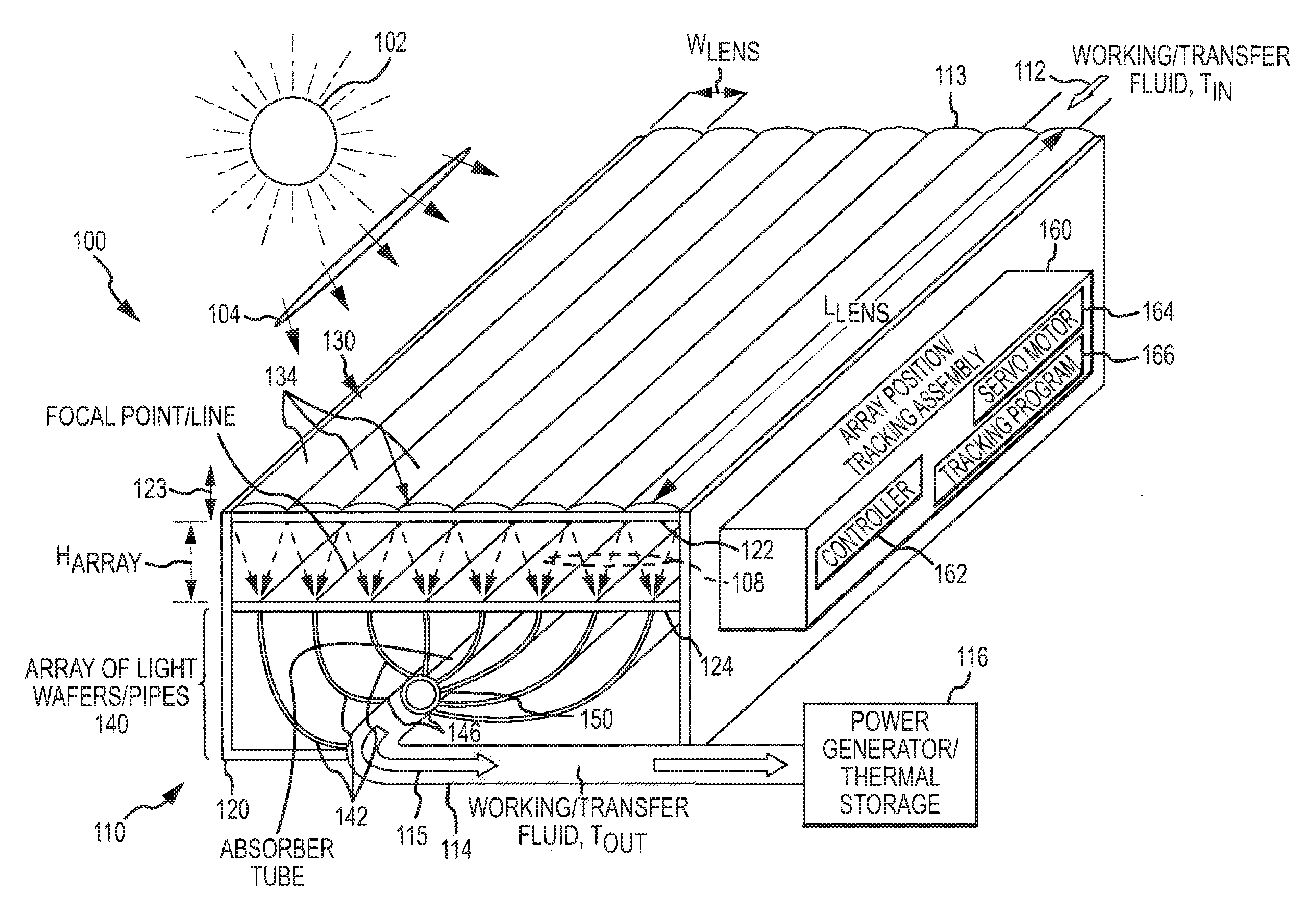
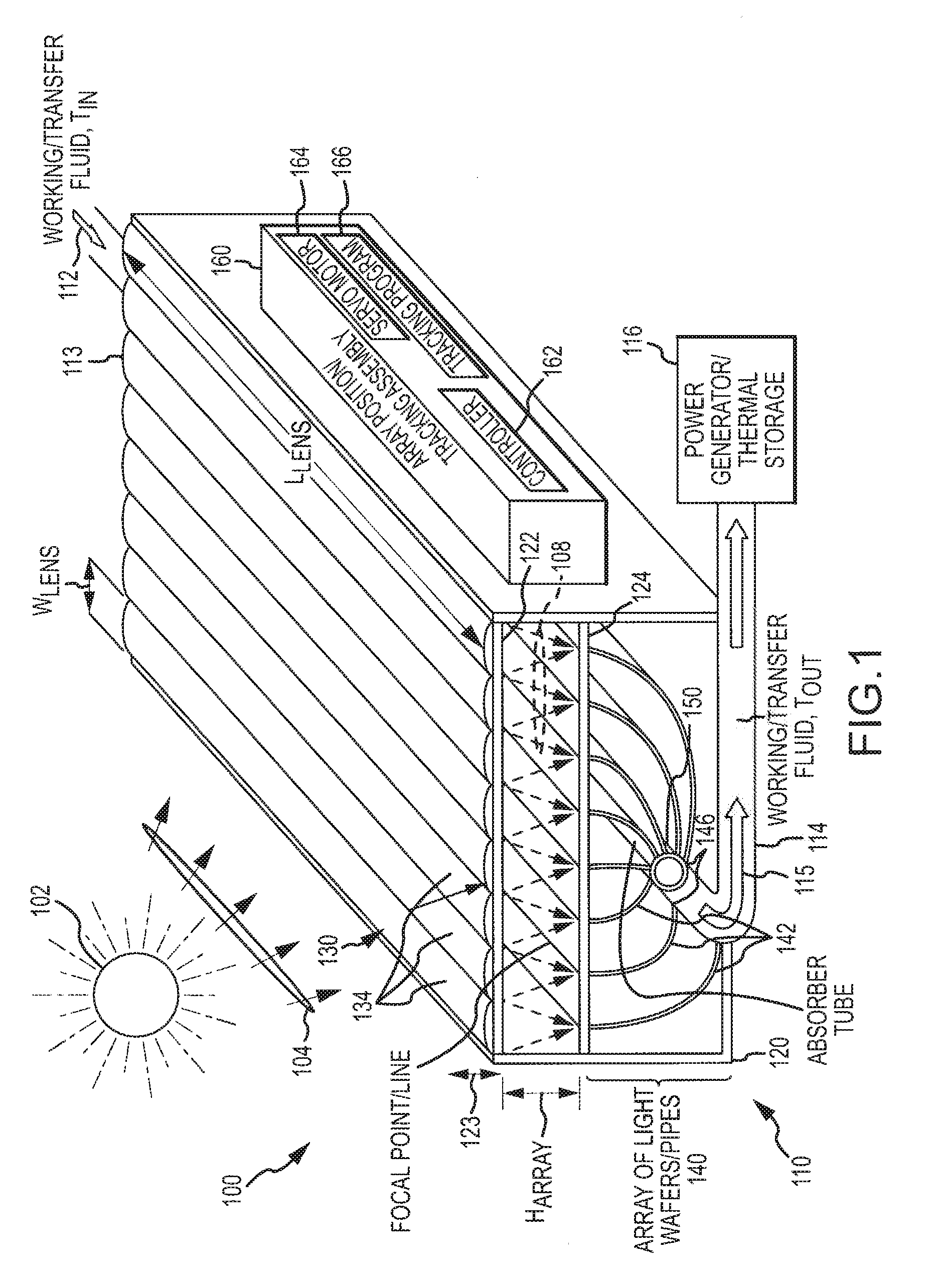
[0031]The present invention is generally directed toward new concentrators or collectors for more effectively collecting solar energy throughout the day and over two or more seasons. FIG. 1 illustrates schematically (or in functional block form) a concentrated solar power (CSP) system 100 of one embodiment. As shown, the CSP system 100 includes a concentrator or collector assembly 110 that combines a lens array with a set or array of light wafers, and the concentrator assembly 110 may be tracking and / or have the lens array be adjustable to adjust for daily and / or seasonal changes in the position of the Sun 102.

[0032]Briefly, the CSP system 100 includes the concentrator assembly 110 that includes a housing 120 in which a lens frame or support 122 is provided near an upper opening. The housing 120 also includes a wafer support or plate 124 that is typically rigidly mounted in the housing 120 and supports a first or receiving end 144 of a plurality of light wafers or pipes 142 (e.g., a...


PUM


Abstract

A solar power system for supplying concentrated solar energy. The system includes a cylindrical absorber tube carrying the working fluid and a concentrator assembly, which includes an array of linear lenses such as Fresnel lenses. The concentrator assembly includes a planar optical wafer paired with each of the linear lenses to direct light, which the lenses focus on a first edge of the wafers, onto the collector via a second or output edge of the wafers. Each of the optical wafers is formed from a light transmissive material and acts as a light “pipe.” The lens array is spaced apart a distance from the first edges of the optical wafers. This distance or lens array height is periodically adjusted to account for seasonal changes in the Sun's position, such that the focal point of each linear lens remains upon the first edge of one of the optical wafers yearlong.

Description

CROSS-REFERENCE TO RELATED APPLICATIONS [0001]This application claims the benefit of U.S. Provisional Application No. 61 / 245,507 filed Sep. 24, 2009, which is incorporated herein by reference in its entirety.BACKGROUND OF THE INVENTION [0002]1. Field of the Invention[0003]The present invention relates, in general, to concentrators for use in the solar power industry, and, more particularly, to systems, devices and methods for more effectively concentrating solar energy (or, more simply, for concentrating sunlight) using an improved tracking concentrator such as a fiber optic wafer concentrator adapted for effective tracking of the Sun.[0004]2. Relevant Background[0005]In general, concentrated solar power systems use lenses or mirrors to focus a large area of sunlight onto a small area. Electrical power is produced when the concentrated light is directed onto photovoltaic surfaces or when the concentrated light is used to heat a transfer fluid for a conventional power plant (e.g., to...

Claims


Application Information

Patent Timeline
IPC IPC(8): F24J2/08F24J2/38F24J2/24F24S10/70F24S23/00F24S23/30F24S50/20
CPCF21S11/00F24J2/067F24J2/085F24J2/244Y02E20/14F24J2/40Y02E10/43Y02E10/44Y02E10/47F24J2/38F24S10/74F24S50/20F24S23/12F24S23/31F24S50/00
Inventor RAYMOND, MARK A.LANGE, HOWARD G.WEISS, SETH
Owner GENIE LENS TECH
Why Eureka
Try Eureka